
 +1 829 698 0733
What Do You Need? Talk To Us
+1 829 698 0733
What Do You Need? Talk To Us8am-4pm EST/NY Monday-Friday info@aareff.com

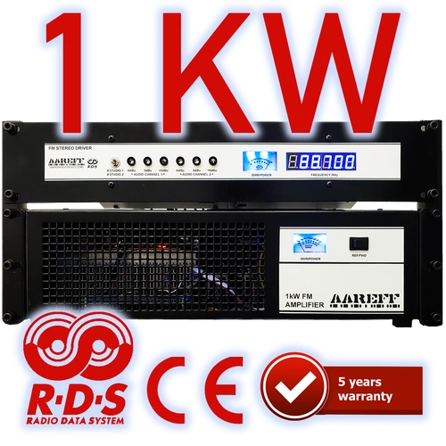
1kW FM Transmitter Stereo DDS with RDS and Audio Processing | AAREFF
- Robust 1kW LDMOS RF Output (Engineered for 24/7 Reliability)
- Built-in Stereo with Advanced Audio Processing
- Dynamic USB/PC Controlled RDS (Radio Data System)
- Rock-Solid DDS Frequency Control (Zero Signal Drift)
- Professional XLR Balanced Audio Inputs for Ultra-Low Noise
- Exceeds CE & FCC Technical Specifications
- Backed by an Industry-Leading 5-Year Warranty
- Includes 100% Free Global Delivery

|
5 YEARS
LIMITED WARRANTY |
Built By Experts. Guaranteed For 5 Years.
This Aareff 1kW FM Transmitter is engineered for serious broadcasting. It includes every feature necessary for a professional station, from the DDS Exciter and Stereo Audio Processing to the Dynamic USB/PC Controlled RDS. High power combined with the right FM antenna (e.g., an 8-bay stacked dipole) can propel your signal up to 100km, creating a formidable 10kW EIRP system.
Superior Engineering & Compliance
- ✔ Robust LDMOS RF Output: Ensures exceptional durability and handles high power demands with ease.
- ✔ DDS Frequency Control: Rock-solid stability to avoid signal drift and maintain licensed accuracy.
- ✔ CE/FCC Compliance: Meets the highest international broadcasting standards for safety and performance.
- ✔ XLR Balanced Input: Professional-grade input eliminates noise for crystal-clear audio quality.
SIMPLE 3-STEP INSTALLATION
Installation is straightforward. Install the antenna, connect the transmitter, then connect your audio source.
1
Install the Antenna
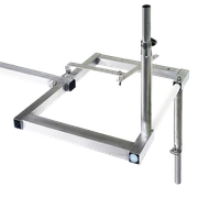
Install correctly for your chosen FM broadcast frequency.
2
Connect the Transmitter
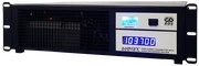
Connect to the antenna system via the 50-ohm cable and plug.
3
Connect Your Audio Source
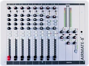
Connect a broadcast mixer console or STL receiver.
Do You Have A Question?

Which Version Do You Need?
Selecting the Optimal Version for Your Broadcast Requirements.
Choosing the correct version of your FM Transmitter is crucial for operational efficiency and meeting your specific broadcast goals. We offer professionally engineered systems that cover 90% of customer requirements right out of the box, ensuring you get the exact functionality needed for your station.
These are the two primary, professional versions of our FM Transmitters:
| ◼ Stereo with RDS and Audio Processing Version | Any station prioritizing high audio quality, professional stereo separation, and dynamic Radio Data System (RDS) functionality for displaying station name, song titles, or slogans. This is the most feature-rich option for modern, professional broadcasting. |
|
The Recommended Choice: Automated Compliance & Performance. If you're uncertain about which system to select, this version is the highly recommended and definitive choice. It provides an ideal combination of power and ease-of-use. -500px.webp)
The audio inputs follow industry standards: 600 ohm +4 dBu balanced, using XLR connectors for professional-grade connections. Additionally, this version comes with built-in RDS, allowing listeners to see your station name and other dynamic messages on car radio displays. This is not just standard RDS—it features fully programmable dynamic RDS. By connecting the transmitter to a PC via USB, you can update RDS data in real time using the USB PC CONTROL function shown below. |
|
| ◼ MPX Version | Experienced engineers who handle external audio processing and stereo encoding outside the transmitter. This version accepts a pre-processed and encoded composite signal (MPX) for direct modulation, offering maximum control to the audio chain expert. |
|
Professional-Grade Raw MPX Input This version is specifically available for experienced users who require a straight, raw MPX input for external signal processing. 1. Zero Tilt for Multiband Processors -500.webp)
2. Ultra-Stable Hartley VCO & Slow-PLL Architecture Result: This preserves the essential low-end audio response demanded by high-performance audio processors. |
|
Need Customization?
We understand that custom requirements exist. If you need alternative versions (e.g., stereo only, no RDS, no processing), we can accommodate these requests to match your specific technical setup.
Contact Our Experts
If you are still unsure, you are always welcome to contact us at:
info@aareff.com
or WhatsApp: +1 829 6980733 and we're more than happy to advise you.
Maximize Your Reach: Choose the Right Antenna
This 1kW transmitter works with any correctly matched 50 ohm antenna with sufficient power handling. For maximum coverage, an Aareff high-gain antenna can concentrate considerably more of that RF power toward your listeners and significantly increase the effective radiated power of the complete system.
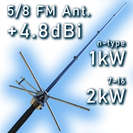
COMPACT HIGH GAIN
5/8 Wave Vertical
A simple high-gain vertical antenna ideal where tower space and installation complexity need to be kept to a minimum.
4.8 dBi Gain | Vertical VIEW ANTENNA →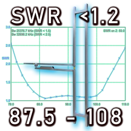
BROADBAND + HIGH POWER
Folded Dipole
Professional broadband antenna covering the complete FM band without retuning and available in very high-power configurations.
87.5-108 MHz | Up to 3kW VIEW ANTENNA →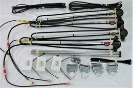
HIGH GAIN ARRAY
4-Way Stacked Dipole
Excellent balance of gain, broadband operation and manageable tower size for serious medium and long-range installations.
7.8 dBi Gain | Broadband VIEW ANTENNA →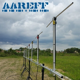
MAXIMUM VERTICAL GAIN
8-Way Stacked Dipole
Our high-gain vertical array concentrates RF energy into a narrow horizontal beam for maximum useful signal toward the horizon.
10.8 dBi Gain | 8-Bay Array VIEW ANTENNA →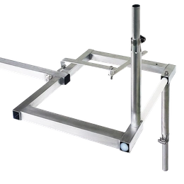
CIRCULAR POLARIZATION
Cycloid Circular FM Antenna
True circular polarization for broadcasters wanting both horizontal and vertical signal components, particularly useful for mobile reception and difficult multipath environments. Also available as stacked high-gain arrays.
Circular | Up to 3kW | Stackable VIEW ANTENNA →
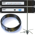
Need a Complete Ready-to-Air System?
Skip the antenna, cable and EIRP calculations. Our complete high-power FM systems combine the transmitter,
low-loss coaxial cable and matched antenna array into a complete package engineered to achieve the required radiated power.
Robust Construction & Enclosure Design
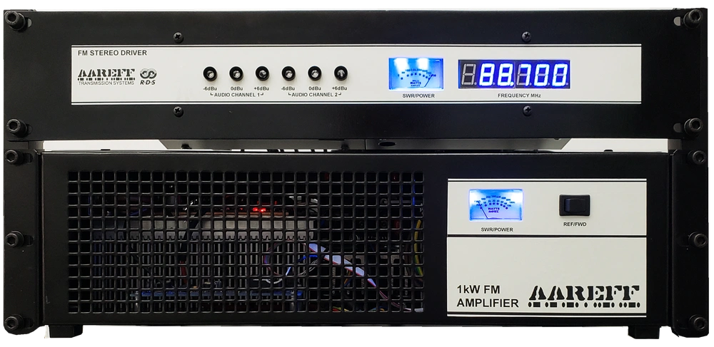
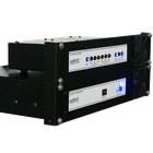
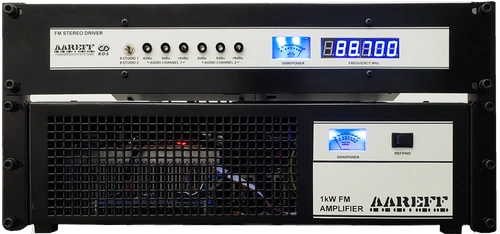
This 1kW system is housed in a robust, dual-enclosure setup (1x 3U, 1x 2U) designed to fit any standard 19-inch rack. Utilizing heavy-duty 16-gauge steel, the metalwork meets high-stress, military-grade requirements. The baked-on satin black powder coating provides a highly scratch-resistant, rust-proof surface.
Fully CE & FCC Compliant
The stereo version with audio processing meets all regulatory standards out of the box. If you send us a copy of your broadcast permit, we will configure the unit exactly to your local specifications before shipping. This equipment strictly complies with EU/CE harmonised standards and FCC technical requirements. View Compliance Details.
Dynamic RDS (Radio Data System) Included

The stereo version comes complete with fully programmable dynamic RDS. Connect the transmitter to a PC via USB, and the circuit will automatically extract the Artist and Song name from your DJ playout software (like Zara Studio) and broadcast it to car radios. Learn more about RDS setup.
VSWR Resilience: The BLF188XR Transistor
The heart of this model's final output stage is the BLF188XR LDMOS RF power transistor. The 'XR' designation stands for 'eXtremely Rugged,' signifying its design for the most demanding engineering environments.
Zero Downtime VSWR Protection:
- Extreme Load Handling: Withstands a severe load mismatch (VSWR greater than 65:1). This ensures unparalleled resilience against real-world antenna failures or lightning strikes.
- Automatic Foldback: Power is automatically and gently reduced to a safe level to prevent any component damage.
- Conservative Operation: While capable of 1600W peak output, we conservatively run it at a maximum of 1kW. This drastically extends the system's longevity and ultra-reliability.
Extreme Temperature Resilience: 24/7 Continuous Performance
Field-Proven Durability: This unit is engineered for the world's most demanding environments. The original design was successfully deployed in East Africa five years ago and remains fully operational 24/7, enduring intense, continuous heat.
Intelligent Protection and Auto-Recovery: Our advanced protection system ensures the longevity of your investment, providing automatic fail-safes without abrupt disruptions.
- Over-Temperature Protection: If internal temps exceed 70°C, the system triggers a gentle RF power back-off (soft reduction) to avoid abrupt cuts. It automatically restores full power when temperatures stabilize.
- Reflected Power Protection: If a high VSWR is detected (indicating an antenna fault), power is safely reduced to prevent damage. It auto-recovers instantly once the fault is cleared.
The Benefit: In the event of extreme heat or antenna damage, the power is safely reduced. Once resolved, the unit restores full power, minimizing station downtime.
LIVE TRANSMITTER DASHBOARD — ON AIR NOW
This dashboard is connected to a live transmitter operating in our workshop. Click
%22/%3E%3Cpath d=%22M25,38 h14 l18,-14 v52 l-18,-14 h-14 z%22 fill=%22%23ffffff%22/%3E%3Cpath d=%22M68,36 l18,28 M86,36 l-18,28%22 stroke=%22%23ffffff%22 stroke-width=%228%22 stroke-linecap=%22round%22/%3E%3C/svg%3E) and, after a couple of seconds, you will hear the real-time audio feeding the transmitter. It works over standard home routers, mobile hotspots and Starlink—no network configuration required.
and, after a couple of seconds, you will hear the real-time audio feeding the transmitter. It works over standard home routers, mobile hotspots and Starlink—no network configuration required.
What you are seeing is not a simulation or a video. Every meter, reading and log on this page is live.
So, in addition to looking super cool, with its BBC PPM audio meter and everything else, what does it actually do? Is it just smoke and mirrors? The answer is a big NO! Unfortunately, there is not enough space on the home page to explain all of its features.
- Accessible from your PC, phone or tablet via LAN, Wi-Fi and STL over RF LAN
- Worldwide internet access via our built-in, free VPN
- Full online HLS encoder—better than Barix
- No outdated Icecast or Shoutcast servers required
- Live public .m3u8 link for submission to TuneIn and other streaming directories—click the DASH URL to test it
- Works with any of our transmitters from 100 mW to 100 kW EIRP
- Transmitter vitals, temperature, phase, frequency, power and more displayed in real time
- Remote adjustment of transmitter parameters via CMD-SERV commands
- AoIP input via HTTP or RTP streams
- Static and dynamic RDS parameters fully adjustable
- Detailed Web, VPN, Network, Device and RDS status logs
- Click on BASIC for even more information
More detailed info in the IPCONNECT DASHBOARD USER GUIDE
Compliance
The stereo version with audio processing and limiting meets all the regulatory standards required out of the box and pre configured. In fact if you send us a copy of your permit and it's conditions, we will set it up exactly to the specification. This equipment complies with EU/CE harmonised standards and FCC technical requirements for FM broadcasting. More information about regulatory compliance
Configuring Power, Dev. and Freq.
Achieving accurate and compliant broadcasting is made simple with the FM Transmitter's integrated tuning features.
Effortless Parameter Adjustment
The three essential broadcasting parameters are designed for easy and precise user setting:
This design guarantees maximum flexibility and simple on-site configuration for any broadcasting requirement. More information on this in the User Manual, you can find a link to this below.
• Operating Frequency (FM Channel)
• Output Power Level (Fine-tuning the 1W output)
• FM Deviation (Modulation depth)
These settings are adjusted via accessible controls on the underside panel. The process is simplified by the inclusion of an integral frequency counter, which allows for real-time visual confirmation and high-precision tuning of your broadcast signal.
For comprehensive, step-by-step guidance on utilizing the integral frequency counter and setting up the underside panel controls, please refer to the official User Manual in the link below..


USER MANUAL
INTENDED USE
i. The equipment in this document is only for use permanently at a pre-defined location with a license or authorisation from the radio spectrum regulator in your country or EU member state.
ii. The installer must have competent RF engineering skills at their disposal, be EMC aware and understand radio frequency systems. The final installation should be in accordance with the EU and the US techincal parameters and the maximum audio deviation level for the full composite MPX signal should be adjusted to b an absoulte maximum for +/-75 KHz.
USA REQUIREMENTS. Section 2.1047 Modulation characteristics and section 2.1049 Occupied bandwidth at:
http://www.gpo.gov/fdsys/granule/CFR-2011-title47-vol1/CFR-2011-title47-vol1-sec2-1047/content-detail.html
EU REQUIREMENTS. Section 8 Audio Processing Limiter at:
https://www.aareff.com/ETR132.pdf
PACKAGE CHECKLIST
| Qty | Description | Item |
| 1 | 1W FM Stereo with RDS and Audio Processing Exciter 15V DC (ALSCXB & 1WPLLB) | 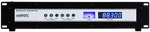 |
| 1 | 1000 FM Power Amplifier | 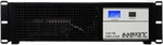 |
| 1 | DC to DC Cable (DC connections from ALSCXB to 1WPLLB) |  |
| 1 | IEC AC Power Cable |  |
| 1 | MPX Audio Cable (Audio connection from ALSCB to 1WPLLB) |  |
| 1 | N Type to BNC Cable (RF connection from 1WPLLB to 1000WNTAP) | |
| 1 | 15V DC Switched Mode AC Power Supply | 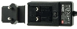 |
| 1 | Rack Rails | 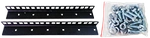 |
ASSEMBLING THE TRANSMITTER
 This must be done by an engineer, technician or other person that has skills and competence in EMC and radio frequency systems. The final installation should be in accordance with the site engineering document at https://www.aareff.com/ETR132.pdf
1. Use the supplied M6 screws, nuts, washers, and rack rail bars to secure the Driver (1WPLLB and ALSCB) and the 1000W Amplifier together as shown in the image. The Amplifier is much heavier, so it should be at the bottom. The Driver is lightweight and should be suspended in the air without any support at the back.
Alternatively, you can mount the units in a 19-inch professional cabinet and integrate them with other equipment you have.
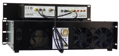
2. Connect the 1000W (1kW) RF OUTPUT of the Amplifier to 50 ohm antenna cable or dummy load
3. Using the supplied N Type to BNC cable, connect the 1 WATT RF INPUT from the Amplifier to the 1 WATT RF OUTPUT on the Driver.
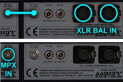
4. Using the MPX Audio cable, connect the ALSCXB MPX OUTPUT to the 1WPLLB MPX INPUT on the Driver.
5. Connect the ALSCXB DC AUX OUTPUT to the 1WPLLB DC INPUT using the short black DC to DC cable on the Driver
CONNECT THE ANTENNA TO THE RF OUTPUT
 The ANTENNA is very important, check this is installed and ready to use. DO NOT EVER POWER A TRANSMITTER OR RF AMPLIFER WITHOUT AN ANTENNA CONNECTED.
PLUG THE ANTENNA CABLE INTO THE TRANSMITTER. Make sure this tight as poor and loose connections can cause RF burns to personnel, severe noise to the transmission and excessive RF bandwidth. A transmitter should never be operated without an antenna. DO NOT PLUG IN THE POWER CORD AT THIS STAGE.
Under NO CIRCUMSTANCES should the antenna be mounted and used at ground level or within a few meters of personnel.
A tuned antenna with the 50 ohm coaxial cable should be used. This should give a return loss ideally of 16dB (SWR 1.4) or better at the operating frequency. The RF plug should be PL259 (UHF) or N type, depending which is fitted to the FM transmitter.
Ensure that all antenna connections are sound, this is important as poor connections and soldered joints can cause RF burns to personnel, severe noise to the transmission and excessive RF bandwidth. Do NOT connect the antenna to the transmitter yet.
Ideally the antenna for this transmitter should be ideally mounted 20 meters high and clear of any surrounding objects to get maximum range and more importantly to reduce risk of radio frequency radiation to personnel. When mounted at 20 meters in height off ground and using 1000 watts of transmitter power, power flux density measurements made at ground level directly under the antennas described above show less than 1 W/m2. Several European countries use a value for the power flux density of 10 W/m2 as a basis for considering whether or not an area is safe. The issue of radio frequency radiation limits is a contentious one and work in this field is continuing worldwide.
BOTTOM PANEL CONTROLS
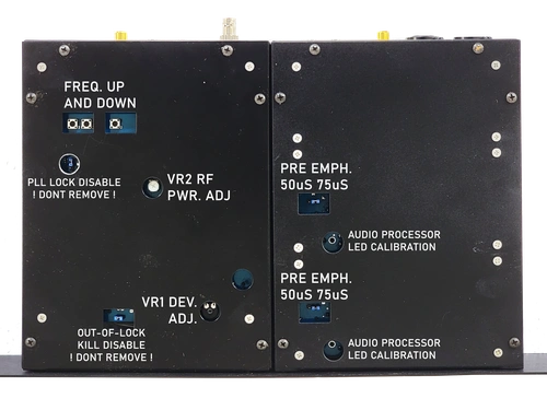
Turn the transmitter upside down to locate the following controls:
If you have the latest model, then you will have the following components:
- VR2 - RF Power Output Control
- Two Small Buttons for Stepping Freq Up and Down.
- VR1 - FM Deviation Control
BE CAREFUL not to be too heavy handed, these controls are only small pcb mounted pots and switches and can be damaged with excessive force. You will need to use a small electrical screwdriver to adjust these controls.
SET THE RF POWER OUTPUT TO ZERO
If you are connected directly to an antenna, as a safety precaution adjust VR2 RF PWR. ADJ fully counter-clockwise. In this counter-clockwise position the transmitter output will have no RF output, it is reduced to zero. IMPORTANT! This is to prevent interference to the radio spectrum if you are not on the correct frequency or not set up properly.
POWERING UP THE DRIVER
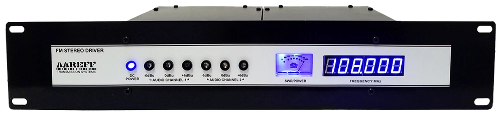
Plug the small 15V DC power supply into the ALSCXB DC INPUT on the Driver and to the AC mains. DO NOT CONNECT THE 1000W (1kW) AMPLIFIER to the AC mains at this point
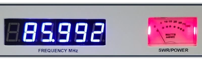
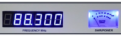
The Driver meter should illuminate RED, then after a second or so turn to BLUE. When the meter is BLUE the Driver is PLL locked on to the DDS reference frequency. If it flashes RED and BLUE and you see various numbers scrolling in the frequency display, don't panic, this is normal, it is doing a recalibration for its new environment and temperature. Please give it a few minutes to complete this.
SET THE FREQUENCY
Locate the two small frequency up and down buttons. These small buttons are used for stepping up or down in selecting a frequency. As you press the up or down buttons, you'll notice the frequency on the digital display change. It's important to select your frequency correctly, if you don't, it's possible to transmit on an unauthorised frequency.
CONNECTING THE AUDIO BASEBAND
Stereo Version The stereo version use standard XLR balanced input (+4dBu nom.) and also has the option for direct MPX input. This is self explanatory how it works. Switch UP for XLR stereo input and switch DOWN for direct MPX input. In the MPX mode, the RDS internally continues to function and is mixed with the incoming MPX signal. If the incoming MPX contains RDS from another source, then internal RDS can be turned off permanently via the USB PC control.
MPX Version The MPX version is exactly the same as stereo version, the only difference being that the XLR connectors and switch are omitted and there is no RDS as standard. RDS can easily be fitted as an option, contact us if this interests you.
CHECKING THE AUDIO DEVIATION
During manufacture and test the audio deviation will be set broadcast standard line of +8dBu peak for +/-75KHz peak deviation at 88.0 MHz. There is a high possibility that this will not be the same level as the audio source feed from your studio, external audio limiter and/or processing device, MPX stereo generator and/or RDS generator. You need to check this as excessive deviation can cause adjacent channel interference to other users of the radio spectrum.
WITHOUT TEST EQUIPMENT
Audio deviation is difficult to measure without proper test equipment and the method described here cannot replace proper test equipment, however if your regulator permits this method it is possible to check the deviation very close to correct level by using a relative comparison. Use a radio receiver tuned to a known high quality, high budget and reputed radio station. For example in the United Kingdom this would be a national BBC station. Feed the audio output of the radio receiver into some VU meter or level indication on a mixer or other audio equipment. Look carefully at the metering level peaks. You will notice the meter peak constantly at a specific level, make a note of this. Place the antenna of radio receiver as close as possible to your transmitter enclosure. Re-tune the radio receiver to your transmitter frequency. Look at the metering again. Adjust VR1 DEV. ADJ. so that your audio constantly peaks at a little lower than the level you noted. When you have achieved this your deviation is a little lower or close to the legal level. The reason for this setting is that it is legal to under deviate, but not-legal to over deviate, with a lack of test equipment
It is better to be under deviating in order to prevent adjacent channel interference until you have proper test equipment available.
WITH TEST EQUIPMENT
Connect the transmitter via a coupler and dummy load to a Spectrum Analyzer, Modulation Analyzer or Deviation Meter. Adjust VR2 RF PWR. ADJ fully ANTI-clockwise. Adjust VR1 DEV. ADJ. for the correct deviation on the test equipment.
POWERING UP THE AMPLIFIER
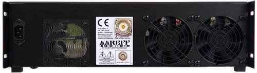
1. IMPORTANT! A properly tuned 50 ohm antenna should be connected to to the main 1kW RF OUTPUT on the Amplifier. DO NOT POWER UP THE AMPLIFER WITHOUT AN ANTENNA CONNECTED
2. The N type to BNC cable should be connected between the 1 WATT RF INPUT from the Amplifier and the 1 WATT RF OUTPUT on the Driver.
3. The Driver should be powered, the meter showing blue and locked to frequency
If the above are confirmed, power up the Amplifier by connecting the IEC mains cable to the AC supply.
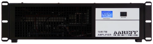
The Amplifier meter will light up blue and you will hear the cooling fans. Set the front panel switch to REF and the meter should read less than 40W.
If the meter is 40W or more, then there is a problem with the antenna, antenna cable or connectors and you should power it down and check the antenna system for faults. Then return to this setion and power up again.
If the meter is less than 40W, then the antenna system is working fine. In this case, set the front panel switch to FWD and the meter should read close to 1000W. If this is the case, everything is working perfectly, the equipment can remain powered and you are ON AIR, permanently
IMPORTANT! ALWAYS KEEP FANS AND VENTILATORS CLEAN
SET THE RF POWER OUTPUT LEVEL
Locate the power control VR2 RF PWR. ADJ. If you followed the previous paragraphs, this power control should be in the counter-clockwise. In the fully clockwise position the transmitter output is at maximum RF output. Check the switch on the front panel is set to FWD. Adjust this control to the desired power level. THE TRANSMITTER IS NOW ON AIR!
USB PC/RDS CONTROL
Download our free PC app that connects 'plug and play' to the transmitter / PLL DDS exciter via USB. You can see the PLL status and change the frequency and power directly from the PC interface. If you choose to add the optional RDS card, you can also change the PI, PTY and scrolling text of the radio from the interface.
Below are the download links for Windows:
https://www.aareff.com/1wpllm/pll14.4/pll14.exe
https://www.aareff.com/1wpllm/pll14.4/pll14.zip
By clicking on these links, Windows may show you a warning that the software is from an unknown publisher. We assure you that we wrote the apps and the files are perfectly safe, virus-free and come from our registered domain www.aareff.com, which you can verify at https://lookup.icann.org/en/lookup
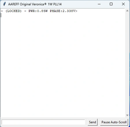
Normal state when the device is connected: the PLL is LOCKED with an output power of 0.85W and a PLL phase of 2.33V
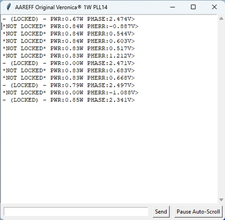
This shows what happens if the device loses its lock. We simulated a failure by placing our fingers on the oscillator coils.
This shows the return to normal with the user command FREQ:106.7 typed in the input box below. A value between 87.5 and 108.0 MHz can be set.
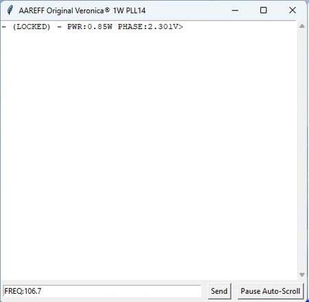
After pressing 'Send:' the display returns UPDATED FREQ 106.7 along with other technical information. This causes the transmitter to change frequency.
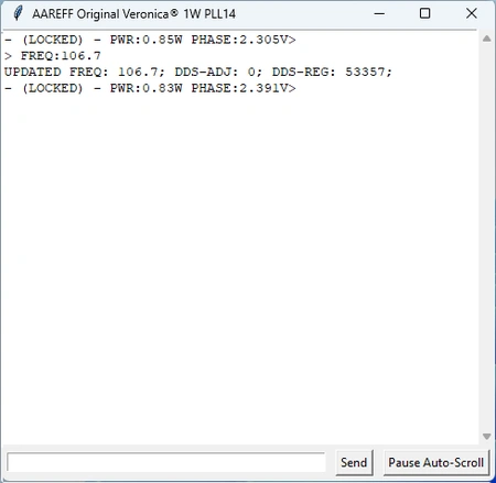
This shows another command, RDS-PI:ABCD typed for devices with the RDS card.
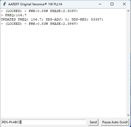
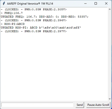
After pressing 'Send': the display returns UPDATED RDS-PI:ABCD instantly updating the RDS PI code.
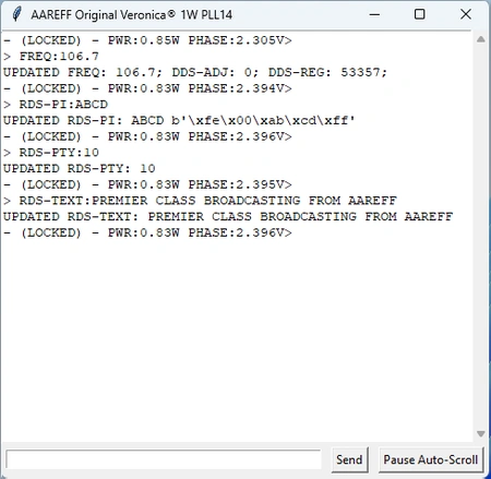
This shows two additional examples of RDS commands:
RDS-TEXT:[write your message here]
RDS-PTY:[number from 0 to 31]
Text is plain ASCII up to 60 chars and valid PTY Codes shown below.
Shown below are the current commands available for USB PC Control and also the PTY codes for program type. We will be making further developments, improvements and more useful commands to this app in the near future. Keep checking this page for details.
◼ DEVICE-ID
◼ STATUS
◼ FREQ:[87.5 to 108.0]
◼ DDS-ADJ:[-1,0 or 1]
◼ PWR:[0 to 1]
◼ RDS-PTY: [0 to 31 list of PTY codes]
◼ RDS-PI: [0000 to FFFF]
◼ RDS-TEXT:[any string up to 60 chars.]
◼ RDS-ON
◼ RDS-OFF
Additional commands following Oct 2025 firmware update
◼ RDS-PS:[any string up to 8 chars.]
◼ RDS-MS:[0 or 1]
◼ RDS-TP:[0 or 1]
◼ RDS-TA:[0 or 1]
◼ RDS-AFNUM:[0 to 15]
◼ RDS-AF:[Up to 15 freq. formatted eg. 88.1, 88.7, 94.8]
◼ RDS-DI:[0 to 31 integer]
◼ RDS-RT:[any string up to 60 chars.]
◼ RDS-SCROLL:[0 or 1]
NORMAL OPERATION
On units with fans fitted should hear the cooling fan. The fan draws air into the front and exits the warm air through the rear vents. It is important to keep these vents clear. The front meter should illuminate in BLUE
The front panel meter should show 1000 watts. If the transmitter power is set to full but you are only seeing 15 to 20% of the power on the meter, it is almost certain, 99% certain, you have a serious antenna problem such as shorted wires or broken wires in the coaxial cable connector or the antenna is incorrectly assembled. This is normal and it is the transmitter reducing the power automatically to protect itself from permanent damage. If you resolve the connector, shorted or broken wires or antenna assembly, the the power will return to 100%.
RF Specification
All stated measurements were made at 220VAC at 27 Deg. Celsius ambient temperature unless stated.
| Power Output | Adj. 1-1000 Watts into 50 ohms |
| Spurious Emissions | Less than -75 dB ref to carrier |
| Harmonic Emissions | Less than -70 dB ref to carrier |
| Freq Stability | +/- 1 KHz max. typ. +/-300 Hz |
| Deviation Sensitivity Stability | +/-2 % max |
| Freq Fine Adj | > +/- 1000 Hz |
| Freq Range | 87.5 to 108 MHz in 100 KHz steps |
| Out of Lock RF Muting | Less than -70 dB ref to carrier |
| Residual AM | Less than 0.5 % |
| Synchronous AM | Less than 0.5 % |
| RF Ruggedness | Any VSWR phase or length of time |
| Output Connector | DIN-716 |
| Operating Temp | -20 to +40 Deg C |
AF Specification
| Pre-emphasis | (50 uS/ 75 uS/ None) Selectable | |
| Audio Input Connector | XLR True Balanced 600 ohm No Ground Ref./ Floating | |
| Audio Input Sensitivity | +4 dBu for +/- 75 KHz dev. | |
| Version | MPX | Stereo and Audio Processor |
| Signal To Noise Ratio | 80dB | 65dB |
| Frequency Response | 30Hz-76KHz | 30Hz-15KHz |
| Audio Distortion | Better than 0.1% / 60dB THD | Better than 0.1% / 60dB THD |
AC Specification
| Input Voltage | 90-264 V AC 135-370 V DC 47-63 Hz |
| Input Power | 1400W for 1000W RF OUT with RF SWR less than 1.5 |
| Working Humidity | 20-90% RH non-condensing |
| Safety Standards | UL60950-1 TUV EN60950-1 BSMI CNS14336 CCC GB4943 J60950-1 approved |
| EMC Emission | Compliance to EN55022 class B EN61000-3-2 3 FCC PART 15 / CISPR22 class B CNS13438 class B GB17625.1 |
| EMC Immunity | Compliance to EN61000-4-2 3 4 5 6 8 11 light industry level criteria A |
MAINTENANCE
The only maintenance the amplifier needs is some periodic cleaning. Following a number of weeks of continuous 24/7 use (specified below), the amplifier should be shut down and disconnected. A technician or engineer needs to take of the top lid by removing the self tapper screws. Using a soft new and clean paint brush with a vacuum clean hose, the dust should be gently brushed and sucked away from all areas inside. Pay particular attention to the actual fans at the rear and the fan vent at front.
The table below shows the recommended number of weeks cleaning should be done for some typical environmental areas.
| WEEKS | SALTY | SANDY | DUSTY | PUBLIC | CLEAN |
| 4 |  |
||||
| 6 | |
|
|||
| 8 | |
||||
| 12 | |
 Do not adjust any factory set internal controls.
Under NO CIRCUMSTANCES should any adjustments be made to the internal controls. Such adjustments could damage the unit and invalidate the warranty and also cause serious interference to other users of the electromagnetic spectrum.
USA TECHNICAL REQUIREMENTS
Some versions of this transmitter do not include internal audio limiting. To maintain compliance with the FCC rules and technical requirements the audio source / feed should be level controlled to prevent over deviation and excessive use of bandwidth by means of an external audio limiter and/or processing device, MPX stereo generator and/or RDS generator. More information on this is at is in section 2.1047 Modulation characteristics and section 2.1049 Occupied bandwidth at http://www.gpo.gov/fdsys/granule/CFR-2011-title47-vol1/CFR-2011-title47-vol1-sec2-1047/content-detail.html
EU REGULATORY REQUIREMENTS
Some versions of this transmitter do not include internal audio limiting. To maintain compliance with the EU ETSI standard the audio source / feed should be level controlled to prevent over deviation and excessive use of bandwidth by means of an external audio limiter and/or processing device, MPX stereo generator and/or RDS generator. More information on this in section 8 Audio Processing Limiter at https://www.aareff.com/ETR132.pdf
This product complies with EMC directive of the European Union. To meet this directive the user or installer must follow the wiring instructions in the this user manual
This equipment is not intended for installation by an unqualified end user, the installer must have competent RF engineering skills and EMC knowledge at their disposal. The whole transmission system, including the antenna system and external audio limiting, should be installed in the EU in accordance with document ETR132, a copy of this is available at https://www.aareff.com/ETR132.pdf
LEGAL ADVICE
We sell this equipment to professionals and organizations in good faith it will be used correctly and legally. Nearly every country in the world require licensing for this type of equipment. It is the customer's responsibility to check relevant laws, directives, regulations and licensing requirements before installing or putting this product into service with an antenna system. You, the customer or user agree to defend, indemnify and hold harmless Aareff Systems Limited, it's employees and agents, from and against any claims, actions or demands, including without limitation legal and accounting fees, alleging or resulting from improper or unlawful use of this equipment.
DECLARATION OF CONFORMITY
European Union
We hereby declare that this equipment complies with;
• ETS 300384 European Telecommunications Harmonised Standard when used with an audio compressor limiter supplied and tested by Aareff
• EN 301489-11 V1.3.1 (2006-05) EMC Electromagnetic Compatibility when used with 1 meter AC mains cord supplied. If the installation engineer needs to extend this cord, this and the audio input cable should be no more than 3 meters in length to remain in compliance with EMC directive.
• 2006/95/EC Directive (2006-12) LVD Low Voltage Directive.
Equipment compliance is possible using equipment from and in conjunction from other manufacturers, but since this is beyond the control of Aareff Systems, Aareff Systems cannot or be expected to guarantee compliance in this situation.
United States
The following list are the FCC technical requirements for FM broadcasting. We confirm and verify that this transmitter complies with the technical requirements.
47 CFR Chapter I Federal Communications Commission sections:
• 73.1560, 2.1046 RF Power
• 73.1545, 2.1055 Frequency Stability
• 73.317, 2.1049 (e)(3) Emission Limitation, Emission Mask
• 73.317, 2.1057, 2.1051 Emission Limits, Spurious Emissions at Antenna Terminal
• 73.317, 2.1057, 2.1053 Emission Limits, Field Strength of Spurious Emissions
ROHS
All components used in this apparatus are RoHS compliant and do not contain above the specified limits in any of the following restricted substances:
- Lead
- Hexavalent Chromium
- Mercury
- Cadmium
- Polybrominated Biphenyls (PBB's)
- Polybrominated Diphenylethers (PBDE's)
PRODUCT END OF LIFE
This apparatus must NOT be disposed of with other domestic waste.
We are fully committed to maintaining our responsibilities to the environment. Owners of apparatus that has reached the end of it's useful life can return it to us for recycling, recondition, reuse or proper disposal. You will be required to pay lowest cost postal service available to ship the apparatus to us. Before shipping please contact us for more important information.
© 2026 AAREFF SYSTEMS LIMITED
ALL RIGHTS RESERVED. Aareff is a trademark of Aareff Transmission Systems. All contents of this document including, but not limited to the images, logos, text, illustrations are protected by copyrights, trademarks and other intellectual property rights which are owned and controlled by Aareff Transmission Systems or by other parties that have licensed their material to Aareff Transmission Systems. This document in part or whole may not be copied, reproduced, republished, uploaded, posted or distributed in any way, including by e-mail, ftp or any other electronic means
Every care has been taken in the preparation of this document, errors in content, typographical or otherwise, may have occurred. If you have comments concerning its accuracy, please contact Aareff Systems Limited (UK)
Support from an Engineer