8am-4pm EST/NY Monday-Friday info@aareff.com

Simple! But Effective. Low Cost FM Transmitter Dipole
Technical Specification
| Version | tdaboth | tdaboth50 |
| Gain | 1.8dBi | 0dBi |
| Max Power | 200 Watts | 50 Watts |
| Cable | 1.5m LMR400 | 12m RG58 |
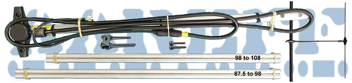
| Frequency | 87.5 to 98 MHz and 98 to 108 MHz | |
| Bandwidth | 10 MHz for an SWR of 1.5 | |
| Construction | Aluminium, Teflon and Ferrite | |
| Connector | UHF/SO-239 or N-Type (optional) | |
| Input Z | 50 ohm unbalanced | |
| Polarisation | Vertical | |
| Weight | 1.4 Kg | |
Do You Have A Question?
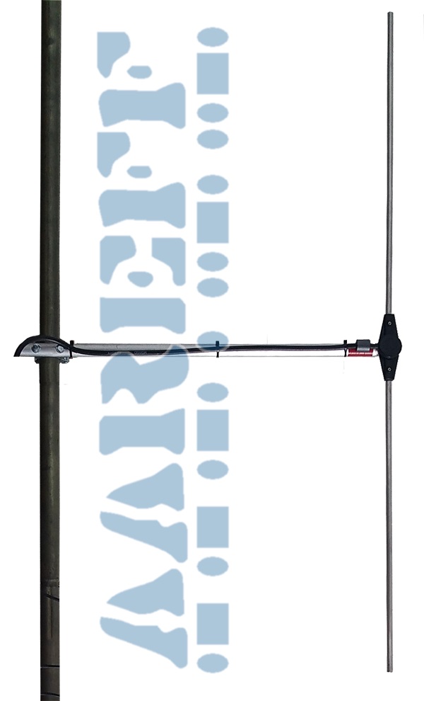
Mounting
Normally the dipole system clamps as high off the ground as possible to a mounting pole of at least 4 meters in length and between 25 and 38mm in diameter which you need to provide and engineer yourself.
Two Versions
Two sets of rods interchaged on the dipole are required to cover the entire FM broadcast band 88-98 MHz and 98-108 MHz. The dipole comes with both sets of rods to cover 87.5 to 98 and 98 to 108. The tdaboth version can handle 200W maximum and has a 1.5 metres LMR400 connection cable. The tdaboth50 version is exactly the same, but uses the lighter cable of RG58 and only handles 50W maximum, but it has 12 metres of RG58 connection cable. We chose 12 metres of RG58 because at 100 MHz it has a loss of exactly 1.8dB. The dipole has a gain of 1.8dB. Therefore the net gain of the dipole and cable is 0dB. This means if you have a 10W transmitter the signal radiated from the antenna is 10W ERP, 30W transmitter, from the antenna 30W ERP. This useful and easy for small stations that have a low powered licence to be able to comply without any complicated calculations. See the all these options in the price panel.
The Best On The Market
As a basic dipole that can handle up to 200W with a unbalanced 50Ω input and less than 1.5 SWR, this is excellent value. It simply is the the best on the market at this price.
True 50Ω Unbalanced Input
Again to provide compatibility with standard transmitter 50 ohm cable we have included a ferrite balun. This keeps the dipole balanced and stops any residual RF currents traveling back down the outside of the cable and thus radiating and potentially causing EMC disturbance to local users.
Let's explain how it works:
1. The dipole has slightly shortened main radials, about 65cm each, which brings the impedance down to 50 ohms but also adds some unwanted series capacitance.
2. The series capacitance is cancelled out by a series inductor of equal reactance inserted in the hot balanced side encapsulated in the terminal box. This leaves close to 50 ohms resistive and starting to look unbalanced, but not fully unbalanced.
3. The hot side is connected to the centre of the LMR400 feed coax and the cold side to the LMR400 outer sheath. There is no electrical connection to the boom, this is electrically floating at DC and RF relative to the LMR400.
4. The LMR400 is immediately passed through a huge ferrite, this ferrite blocks nearly all the remaining RF currents still present on the balanced cold side.
5. The LMR400 is clamped tight to the boom, any residual RF currents still present on the outer sheath of the LMR400, less than 5%, are clamped to ground due to the capacitance formed between the outer braid of the LMR400, the PVC outer plastic covering and the boom which is at mast ground.
6. At the end of the 2m LMR400 feeder cable to the dipole there are no residual RF currents present on the outer sheath, it is fully unbalanced and 50 ohms at the center frequency.
Simple and Easy
The dipole is the simplest of all the FM antennas with a small amount of gain, 1.8dBi.If you require more gain, please check the 2 way 4.8dBi, the 4 way 7.8dBi and the 8 way 10.8dBi stacked dipoles based on this model. Dipoles inherently have a 72Ω impedance across their terminals in free space or air. So that the dipole can be used with standard 50Ω transmitter coaxial cable, we have fitted a matching coil inside centre plastic terminal box. To keep the feeder entry and the matching coil water proofed, the whole terminal box is filled with plastic resin.
Long Life and High Reliability
This was the first of many antennas that we designed back in 1996. There are some still in service that were sold that year, that is long life!. This antenna is usually used with the 100mW, 1W, 10W and 30W transmitters. Our 1W ERP and 30W ERP packages include the 50W version of this antenna. LIke all our antennas, it has been installed in just about every area of the world without suffering wind, corrosion or other weather problems. It will last upward of 15 years with little maintenance.


