8am-4pm EST/NY Monday-Friday info@aareff.com

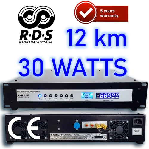
30W FM Transmitter Stereo DDS with RDS and Audio Processing | AAREFF
- 30 WATTS RF OUTPUT FOR UP TO 12 KM COVERAGE
- SUPER SILENT OPTION
- STEREO WITH AUDIO PROCESSING OPTION
- DYNAMIC USB/PC CONTROLLED RDS
- DDS FREQUENCY CONTROL
- ROBUST LDMOS RF OUTPUT
- XLR BALANCED INPUT
- INCLUDES SHIPPING & 5-YEAR LIMITED WARRANTY
- EXCEEDS CE/FCC TECHNICAL SPECIFICATION

|
5 YEARS
LIMITED WARRANTY |
Aareff 30W: The Precision Solution for Targeted Broadcasting
The Aareff 30W FM Transmitter is a professional-grade workhorse with a legendary track record of durability since 1999. Engineered for high-fidelity local coverage with a reliable range of up to 12 km, it provides the ideal balance of power and precision for low-power regulated environments.
🛡️ Over-Engineered Architecture
Designed with an over-rated 45W transistor and a 5-Year Limited Warranty to ensure effortless 24/7 operation in even the most demanding climates.
Designed with an over-rated 45W transistor and a 5-Year Limited Warranty to ensure effortless 24/7 operation in even the most demanding climates.
📡 Niche Application Focus
Specifically optimized for Low Power FM, Drive-In Cinemas, and Restricted Service Licences (RSL) in the UK and Australia.
Specifically optimized for Low Power FM, Drive-In Cinemas, and Restricted Service Licences (RSL) in the UK and Australia.
This system is the premier choice for University Campuses, Houses of Worship, and Emergency Pop-up Stations. Beyond North America, it serves as the backbone for Rural Community Radio in Latin America and Safety Broadcasts for Mining Operations in Canada and Australia. Whether used as a standalone local signal or a high-stability exciter, the Aareff 30W delivers unmatched spectral purity.
Do You Have A Question?


RF Specification
All stated measurements were made at 220VAC at 27 Deg. Celsius ambient temperature unless stated.
| Power Output | Adj. 1-30 Watts into 50 ohms |
| Spurious Emissions | Less than -75 dB ref to carrier |
| Harmonic Emissions | Less than -70 dB ref to carrier |
| Freq Stability | +/- 1 KHz max. typ. +/-300 Hz |
| Deviation Sensitivity Stability | +/-2 % max |
| Freq Fine Adj | > +/- 1000 Hz |
| Freq Range | 87.5 to 108 MHz in 100 KHz steps |
| Out of Lock RF Muting | Less than -70 dB ref to carrier |
| Residual AM | Less than 0.5 % |
| Synchronous AM | Less than 0.5 % |
| RF Ruggedness | Any VSWR phase or length of time |
| Output Connector | N-Female |
| Operating Temp | -20 to +40 Deg C |
AF Specification
| Pre-emphasis | (50 uS/ 75 uS/ None) Selectable | |
| Audio Input Connector | XLR True Balanced 600 ohm No Ground Ref./ Floating | |
| Audio Input Sensitivity | +4 dBu for +/- 75 KHz dev. | |
| Version | MPX | Stereo and Audio Processor |
| Signal To Noise Ratio | 80dB | 65dB |
| Frequency Response | 30Hz-76KHz | 30Hz-15KHz |
| Audio Distortion | Better than 0.1% / 60dB THD | Better than 0.1% / 60dB THD |
AC Specification
| Input Voltage | 90-264 V AC 135-370 V DC 47-63 Hz |
| Input Power | 60W for 30W RF OUT with RF SWR less than 1.5 |
| Working Humidity | 20-90% RH non-condensing |
| Safety Standards | UL60950-1 TUV EN60950-1 BSMI CNS14336 CCC GB4943 J60950-1 approved |
| EMC Emission | Compliance to EN55022 class B EN61000-3-2 3 FCC PART 15 / CISPR22 class B CNS13438 class B GB17625.1 |
| EMC Immunity | Compliance to EN61000-4-2 3 4 5 6 8 11 light industry level criteria A |
Stereo, RDS, and Advanced Audio Processing FM Transmitter Version
The Ideal Transmitter: Loud, Legal, and Hassle-Free
For Beginners: Features automatic audio level adjustment to ensure your 30 watt transmitter always complies with state regulatory specifications. Effortless setup guaranteed.
For Professionals: Skip manual adjustments. This unit is housed in a single, integrated enclosure, providing everything needed for optimal performance without external clutter.
Smart Audio Processing & Regulatory Compliance
The built-in audio processing is engineered for maximum competitive advantage:
• It achieves a loud, impactful audio level while strictly preventing over-deviation and potential regulatory issues.
• The internal audio processors and stereo functionality are expertly calibrated to maintain the crucial balance between maximum loudness and legal compliance.
-500.webp)
The audio inputs conform to the industry standard: 600 ohm +4 dBu balanced, using XLR connectors.
Additionally, this version INCLUDES RDS, allowing your station name and other information to scroll across car radio displays.
This is not just ordinary RDS; it features fully programmable dynamic RDS. By connecting the transmitter to a PC via USB, you can modify the RDS data in real-time using the USB PC CONTROL shown below.
Antennas
On delivery the equipment is ready to plug in and use with any suitable 50 ohm antenna system such as our:
• SINGLE DIPOLE
• 4.8dBi 2 DIPOLES
• 7.8dBi 4 DIPOLES
• 10.8dBi 8 DIPOLES
• 4.8dBi 5/8 ANTENNA
• -0.8dBi CIRC. DIPOLE
• FOLDED DIPOLE
Our system package the 30W EIRP system includes this transmitter with a dipole antenna and very low loss LMR400 cable to give you a full system that will comply with the regulations of the European Union and most other countries in the world.
Flat 30Hz to 76KHz MPX Input Version: Precision for High-End Audio Processors
Professional-Grade Raw MPX Input
This version is specifically available for experienced users who require a straight, raw MPX input for external signal processing.
1. Zero Tilt for Multiband Processors
• The absolute requirement for professional processing is a flat low-frequency response. As proven by our 160Hz Square Wave Test, our input delivers a perfectly square wave with zero tilting. This allows your external processor to maintain absolute control over the modulation, ensuring maximum loudness and a legal signal without low-end artifacts.
-500.webp)
2. Ultra-Stable Hartley VCO & Slow-PLL Architecture
Superior performance starts with a stable foundation. Our Hartley-based, lightly coupled push-pull VCO is so stable it stays within 10kHz of its frequency even with the PLL turned off. This inherent stability leads to two critical performance benefits:
• Ultra-Low Noise: Because the VCO is naturally stable, the PLL only needs to make microscopic corrections (less than 300Hz), resulting in an exceptionally clean and transparent noise floor.
• Preserved Low-End: By heavily low-pass filtering the PLL control voltage to just a few Hz, we ensure 30Hz bass notes pass through the varicap completely unaltered. This preserves the essential low-frequency response demanded by high-performance audio processors.
Result: This preserves the essential low-end audio response demanded by high-performance audio processors.
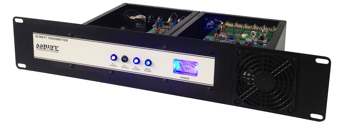
Reliability & Construction
The enclosure is made in strong 16 gauge steel, powder coated and baked in satin black. This leaves a tough, durable surface that will never rot or corrode and be cleaned to shine for decades. The front panel is 19 inch across and 2U (3.5 inch) high with a depth of 12 inches, so it will fit with ease into a standard rack. It is very strong and difficult to damage even under extreme handling.
The output transistor can handle any amount of reflected power comfortably with a a rating of 45 watts on a more than sufficient large heatsink for cooling.
Super Silent ADDED Option
What is SUPER SILENT? it means it's as quiet as a mouse and can use it in a live mic studio without background noise. The video demonstrates the 100 watt transmitter, but it is exactly the same for the 30 and 50 watt units.
If you want SUPER SILENT option, MAKE SURE YOU ADD IT AS AN OPTION in the price panel below.
SUPER SILENT means less 20dBA, this is comparable to a low level whisper in a studio, the chances are other equipment, air con or studio ventilation is higher in volume.
Why Choose AAREFF 30W Transmitter?
Discover the proven AAREFF 30W DDS FM Transmitter:
• Proven worldwide since 1999—still used by clients after 20+ years.
• Durable construction from powder-coated steel.
• Professional design fits standard 19” rack (2U height).
• RF output transistor and oversized heatsink for maximum reliability.
• Easy setup frequency, deviation, power adjustable in minutes.
• Delivery included to your country.
• Robust warranty and direct support from broadcast experts.
LIVE TRANSMITTER DASHBOARD — ON AIR NOW
This dashboard is connected to a live transmitter operating in our workshop. Click
%22/%3E%3Cpath d=%22M25,38 h14 l18,-14 v52 l-18,-14 h-14 z%22 fill=%22%23ffffff%22/%3E%3Cpath d=%22M68,36 l18,28 M86,36 l-18,28%22 stroke=%22%23ffffff%22 stroke-width=%228%22 stroke-linecap=%22round%22/%3E%3C/svg%3E) and, after a couple of seconds, you will hear the real-time audio feeding the transmitter. It works over standard home routers, mobile hotspots and Starlink—no network configuration required.
and, after a couple of seconds, you will hear the real-time audio feeding the transmitter. It works over standard home routers, mobile hotspots and Starlink—no network configuration required.
What you are seeing is not a simulation or a video. Every meter, reading and log on this page is live.
So, in addition to looking super cool, with its BBC PPM audio meter and everything else, what does it actually do? Is it just smoke and mirrors? The answer is a big NO! Unfortunately, there is not enough space on the home page to explain all of its features.
- Accessible from your PC, phone or tablet via LAN, Wi-Fi and STL over RF LAN
- Worldwide internet access via our built-in, free VPN
- Full online HLS encoder—better than Barix
- No outdated Icecast or Shoutcast servers required
- Live public .m3u8 link for submission to TuneIn and other streaming directories—click the DASH URL to test it
- Works with any of our transmitters from 100 mW to 100 kW EIRP
- Transmitter vitals, temperature, phase, frequency, power and more displayed in real time
- Remote adjustment of transmitter parameters via CMD-SERV commands
- AoIP input via HTTP or RTP streams
- Static and dynamic RDS parameters fully adjustable
- Detailed Web, VPN, Network, Device and RDS status logs
- Click on BASIC for even more information
More detailed info in the IPCONNECT DASHBOARD USER GUIDE
Compliance
The stereo version with audio processing and limiting meets all the regulatory standards required out of the box and pre configured. In fact if you send us a copy of your permit and it's conditions, we will set it up exactly to the specification. This equipment complies with EU/CE harmonised standards and FCC technical requirements for FM broadcasting. More information about regulatory compliance
Precision Control: Frequency, Power, and Deviation
Adjusting frequency and power levels is straightforward yet secure. To prevent accidental or unauthorized changes, we have engineered a hardware-based compromise by placing essential controls on the underside of the chassis. By simply sliding the unit out of the rack and inverting it, you gain direct access to the DIP switches and trim pots for precise calibration.
This professional design ensures that critical broadcast parameters—including frequency, power output, and FM deviation—remain exactly where you set them. This manual configuration method offers a layer of physical security that software-only buttons cannot match, protecting your station from inadvertent interference or regulatory violations.


USER MANUAL
INTENDED USE
i. The various pieces of equipment in this document are only for use permanently at a pre-defined location with a license or authorisation from the radio spectrum regulator in your country or EU member state.
ii. The installer must have competent RF engineering skills at their disposal, be EMC aware and understand radio frequency systems. The final installation should be in accordance with the site engineering document at https://www.aareff.com/ETR132.pdf The radio station management must assign a responsible person to the transmission equipment and installation.
PACKAGE CHECKLIST
| Qty | Description | Item |
| 1 | 30W FM Transmitter | |
| 1 | IEC AC power cord | 
|
| 1 | BNC to BNC 50 ohm Cable |  |
| 1 | DC to DC Lead (DC connection 1WPLLB to 30WNTA) |  |
| 1 | 90 Watt External Switch Mode 90-260V AC / 15V DC Power Supply |  |
THIS TRANSMITTER COMES IN THREE VERSIONS
MPX. - This is the low cost version, it's not intended for the novice or beginners. The audio input is raw MPX without any audio limiting or stereo coder circuitry, this must be provided externally in accordance with the recommendations ofhttps://www.aareff.com/ETR132.pdf
Versión estéreo. - This is identical to MPX version but with a stereo coder built in. Again it does not include audio limiting, so it's not recommended for the novice or beginner. External limiting need to comply with the recommendations of https://www.aareff.com/ETR132.pdf
Stereo and Audio Processing. - Most small radio stations and beginners will use this version, this is because it includes audio processing circuitry and suitable limiting to keep the transmitter in compliance with the maximum bandwidth permitted by the international regulations. There is also access to the MPX in and out on the back panel which allows all known RDS units to be connected.
USA TECHNICAL REQUIREMENTS
Some versions of this transmitter do not include internal audio limiting. To maintain compliance with the FCC rules and technical requirements the audio source / feed should be level controlled to prevent over deviation and excessive use of bandwidth by means of an external audio limiter and/or processing device, MPX stereo generator and/or RDS generator. More information on this is at is in section 2.1047 Modulation characteristics and section 2.1049 Occupied bandwidth at http://www.gpo.gov/fdsys/granule/CFR-2011-title47-vol1/CFR-2011-title47-vol1-sec2-1047/content-detail.html
EU REGULATORY REQUIREMENTS
Some versions of this transmitter do not include internal audio limiting. To maintain compliance with the EU ETSI standard the audio source / feed should be level controlled to prevent over deviation and excessive use of bandwidth by means of an external audio limiter and/or processing device, MPX stereo generator and/or RDS generator. More information on this in section 8 Audio Processing Limiter at:
https://www.aareff.com/ETR132.pdf
This product complies with EMC directive of the European Union. To meet this directive the user or installer must follow the wiring instructions in the this user manual
This equipment is not intended for installation by an unqualified end user, the installer must have competent RF engineering skills and EMC knowledge at their disposal. The whole transmission system, including the antenna system and external audio limiting, should be installed in the EU in accordance with document ETR132, a copy of this is available at:
https://www.aareff.com/ETR132.pdf
DESIGN
The design uses two separately enclosed units joined together. The first unit, 1WPLLB, is the driver. This is a low power VHF oscillator amplified to 1 watt of power and is phase-locked via a divider chain to a reference oscillator. The 1 watt signal is filtered to the permitted levels and produces RF at the driver 1W 50 Ohm Output
The second unit, 30WNTA, is the amplifier. This takes the 1W signal at the 1W 50 Ohm Input from the driver and immediately reduces it to 300mW using a resistive attenuator. The purpose of this is to add a real resistive load (without reactance) to the input of the amplifier; this provides absolute RF stability and prevents parasitic oscillations from starting. The 300mW signal is then amplified to 3W. The 3W is then amplified to 30W. The 30W signal is impedance matched by a broadband two stage LC network to 50 ohms. Finally before arriving at the 30W 50 Ohm Output the 30W signal is passed through a ten pole LC low pass filter.
Both units are housed in metal fully screened enclosures to protect the user from direct contact with RF voltages and to prevent unwanted emissions, local interference and provide the RF units with adequate immunity for the proper operation in an industrial environment. It is possible to use each unit separately and independently on a “stand alone” basis from each other.
INSTALLING THE TRANSMITTER
 The installation must be by an engineer that has skills and competence in EMC and radio frequency systems. The final installation should be in accordance with the site engineering document at:
https://www.aareff.com/ETR132.pdf
DON'T APPLY THE POWER SUPPLY JUST YET
BACK PANEL
The MPX version is shown here. The back panel of the stereo version is the same only with the exception of an additional RCA/Phono input for left and right stereo audio.
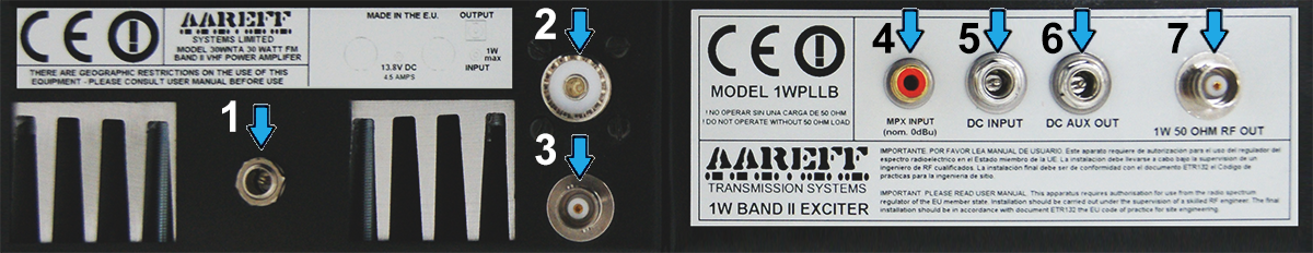
| 1 | 30W Amplifier DC 15V 4.5A Input |
| 2 | 30W 50 Ohm RF Output |
| 3 | 1W 50 Ohm RF Input |
| 4 | MPX Input 0dBu 10K ohm |
| 5 | DC Input 15V |
| 6 | Auxiliary DC Output 15V |
| 7 | 1W 50 Ohm RF Output |
A) MPX Input
MPX is an abbreviation for Multiplex signal. Multiplex is the name commonly used to describe the encoding of stereo audio signal band developed by Zenith / GE and used for standard stereo FM broadcasting. MPX Input also accepts simple mono audio signals and RDS (Radio Data System) or a combination thereof. The connector is RCA / phono type unbalanced with a 'Hi-Z' input of 10k ohms. You must use high quality shielded cable to connect the coaxial input for the other equipment. During the factory test the exciter is adjusted to give + / -75 kHz deviation FM (maximum allowed) at 88.0 MHz for +4 dBu input.
To comply with the EMC Directive the cable used to connect this input to the other equipment should not exceed 3 meters in length. To comply with the R&TTE directive it is mandatory that the level of the MPX signal is limited with an audio peak limiter or similar processor. After the installation the deviation of the FM needs to be reviewed and adjusted so that the peak limited MPX signal gives a maximum deviation of not more than + / -75 KHz. The setting of this deviation is VR1 and shown in the picture the bottom panel.
B) DC INPUT and DC AUX OUT
The DC INPUT and DC AUX OUT are simply connected together inside the unit. The purpose of this is to provide a DC connection to the 30WNTA amplifier from the 1WPLLB driver in the form of a 'daisy chain' and therefore they can share the same power supply.
Use the short black DC to DC cable and connect 1WPLLB driver DC AUX OUT connector to the 30WNTA amplifier 15V DC connector
C) 1W 50 OHM OUT and 1W 50 OHM IN
This is the RF output of 1W 1WPLLB driver and the RF input of the 30WNTA amplifier both these terminations are 50 ohm. Connect these together using the supplied black BNC to BNC cable
Bottom Panel
Please refer to picture of the bottom panel. Turn the transmitter upside to show the bottom panel controls.
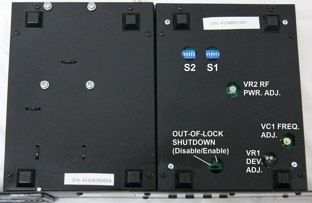
- Power Control VR2 RF PWR. ADJ
- 6 Way Dip Switches S2 and S1
- Deviation Control VR1 DEV. ADJ
- VC1 FREQ. ADJ
- OUT-OF-LOCK SHUTDOWN
BE CAREFUL not to be too heavy handed, these controls are only small PCB mounted pots and switches and can be damaged with excessive force. You will need to use a small electrical screwdriver to adjust these controls.
D) Out of Lock Shutdown
Check that the jumper is fitted to the enable position.
This jumper ensures the transmitter power output is muted to zero when there is no PLL lock. When connected to an antenna, this should always be in the enable position.
The disable position should only be selected when the transmitter is connected to a dummy load and there is a requirement to service or test the transmitter, any other condition it is important that the enable position is selected.
E) Reducing The RF Output To Zero
Adjust VR2 RF PWR. ADJ fully anti-clockwise. In this fully anti-clockwise position the transmitter is set to minimum power, basically it has no RF output.
F) Setting the RF Frequency Dip Switches
Locate the two banks of 6 way dip switches S2 and S1. Select from the table in section DIL SWITCH (S2 and S1) of this user manual your frequency, then set the tiny dip switches to the ON or OFF position as shown in the table. These switches will determine the start up frequency for the transmitter, so, it’s very important they are correct. If they are not correct it’s possible to transmit on an unauthorised frequency.
Double check again in section DIL SWITCH (S2 and S1) that the dip switches are in the correct positions. Make sure they are pushed fully into the ON position or OFF position, not halfway between.
Front Panel
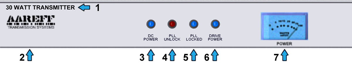
| 1 | Transmitter Model |
| 2 | Manufacturer |
| 3 | Power Indicator |
| 4 | PLL Unlocked |
| 5 | PLL Locked |
| 6 | 1W Drive RF Output Power |
| 7 | Power Meter |
G) Powering the Transmitter
Double check the power is reduced to zero as described in paragraph E) Reducing the RF Output to Zero. At this point the antenna should NOT be connected. Connect the DC Source or AC Power Supply to the AC and DC INPUT on the 1WPLLB driver. Observe the front panel Power Meter, The Power Meter should show zero. If the Power Meter shows zero then continue to the next step.
H) Locking the PLL
It may be by chance that the PLL is close to lock and the front panel LED PLL LOCK has lit up in BLUE. If this is not the case and the front panel LED PLL UNLOCK is lit up in RED, then adjust in any direction VC1 FREQ. ADJ. slowly, be patient and continue to turn slowly until the PLL LOCK lights up BLUE, then STOP turning. The BLUE PLL LOCK indicates PLL lock. The Power Meter should continue to indicate zero, if the Power Meter is showing anything above ZERO please check again paragraph E) Reducing the RF Output to Zero
I) Checking The Transmitter Frequency
- WITHOUT TEST EQUIPMENT
Place the antenna of a digital radio receiver as close as possible, basically right next to your transmitter enclosure. Tune the radio receiver to your transmitter frequency. You should hear the transmitter FM carrier. To verify this apply audio to the transmitter MPX INPUT socket and you should hear this audio on the radio receiver. If you do not hear any FM carrier or audio, work through previous section again carefully. - WITH TEST EQUIPMENT
Connect the transmitter to a 30W or more Attenuator or Dummy Load and a Frequency Counter. Adjust VR2 RF PWR. ADJ a little ANTI-clockwise to show a little power on the Power Meter, this should be enough to get a reading on the Frequency Counter. If the frequency is not correct then work through previous section again carefully
J) Checking the Audio Deviation
The audio deviation will be set close to correct level during manufacture and test, however it is still better to check this again as excessive deviation can cause adjacent channel interference to other users of the radio spectrum. Apply the peak level audio you are going to use from your studio, link, stereo coder or RDS generator to the transmitter MPX INPUT socket (this should be as close to +6dBu as possible) this is typical level of professional studio and radio equipment.
- WITHOUT TEST EQUIPMENT
Audio deviation is difficult to measure without proper test equipment and the method described here cannot replace proper test equipment, however some regulators in some EU member states may permit this method to check the deviation. It is possible to get very close to correct level by using a relative comparison.
Use a radio receiver tuned to a known high quality, high budget and reputed radio station. For example in the United Kingdom this would be a national BBC station. Feed the audio output of the radio receiver into some VU meter or level indication on a mixer or other audio equipment. Look carefully at the metering level peaks. You will notice the meter peak constantly at a specific level, make a note of this.
Place the antenna of radio receiver as close as possible to your transmitter enclosure, basically right next to it. Re-tune the radio receiver to your transmitter frequency. Look at the metering again. Adjust VR1 DEV. ADJ. so that your audio constantly peaks at exactly the same level as noted. When you have achieved this, your deviation is very close to the correct legal level. - WITH TEST EQUIPMENT
Connect the transmitter via a coupler and dummy load to a Spectrum Analyzer, Modulation Analyzer or Deviation Meter. Adjust VR2 RF PWR. ADJ ANTI-clockwise to the required power level. Adjust VR1 DEV. ADJ. for the correct deviation on the test equipment.
K) Preparing to Connect the Antenna
If all paragraphs in this section INSTALLING THE TRANSMITTER are complete, then disconnect the transmitter from the DC Power Source or AC Power Supply. The transmitter is now ready for connection to the antenna. Please read the next section before re-powering the transmitter.
ANTENNA
 Incorrect antenna and /or bad feeder cable connections can cause light RF burns and levels of RF exposure above the recommended limits for personnel
The RF output of this unit should be connected to:
- drive the 50 ohm input of another amplifier or;
- connected to an antenna and feeder cable that presents 50 ohm load (SWR 1.4 or less, 16 dB or more return loss) at the operating frequency.
Under no circumstances should the RF OUT be left open and unconnected if the power output of the unit is set higher than zero.
Ideally the antenna should be mounted at least 20 meters high and clear of any surrounding objects to get maximum range and more importantly to reduce risk of radio frequency radiation to personnel. When an antenna with 3dBi or higher gain towards the horizon is mounted at least 20 meters in height off ground and using up to 30 watts of transmitter power, power flux density measurements made at ground level directly under the antenna show less than 1 W/m2. Several European countries use a value for the power flux density of 10 W/m2 as a basis for considering whether or not an area is safe. The issue of radio frequency radiation limits is a contentious one and work in this field is continuing worldwide.
Under NO CIRCUMSTANCES should the antenna be mounted and used at ground level next to personnel.
Ensure that all antenna connections are sound, this is important as poor connections and soldered joints can cause RF burns to personnel, severe noise to the transmission and excessive RF bandwidth. Do NOT connect the antenna to the transmitter yet.
OPERATION
A) Connecting the Antenna
Connect the antenna to the 30W 50 Ohm Output located on the back panel. The connector should be SO239 or N Type. It should be soldered correctly and be screwed tight, this is important as poor connections and soldered joints can cause RF burns to personnel, severe noise to the transmission and excessive RF bandwidth.
B) Power up the Transmitter
Connect the DC Source or AC Power Supply to the AC and DC INPUT on the 1WPLLB driver. The LED PLL UNLOCK should light up RED for a few seconds, and then the BLUE PLL LOCK should light indicating lock. If this does not happen, please refer again to paragraph F) Setting the RF Frequency Dip Switches
C) Setting the RF Output Power
Locate the VR2 RF PWR. ADJ on the bottom panel. For 30W (maximum) turn VR2 clockwise. For virtually zero power output (about 30 mW) turn VR2 fully anti-clockwise. No other adjustments are necessary. Using the front panel Power Meter adjust the power to the required level.
CONGRATULATIONS YOU ARE NOW ON AIR !
CONTROL DE PC POR USB
Descarga nuestra aplicación gratuita para PC que se conecta 'plug and play' al transmisor / excitador PLL DDS a través de USB. Puedes ver el estado del PLL y cambiar la frecuencia y la potencia directamente desde la interfaz del PC. Si eliges agregar la tarjeta RDS opcional, también puedes cambiar el PI, PTY y el texto desplazable de la radio desde la interfaz.
A continuación, se encuentran los enlaces de descarga para Windows:
https://www.aareff.com/1wpllm/pll14.4/pll14.exe
https://www.aareff.com/1wpllm/pll14.4/pll14.zip
Al hacer clic en estos enlaces, Windows puede mostrarte una advertencia de que el software proviene de un editor desconocido. Te aseguramos que nosotros escribimos las aplicaciones y que los archivos son completamente seguros, están libres de virus y provienen de nuestro dominio registrado www.aareff.com, que puedes verificar en https://lookup.icann.org/en/lookup
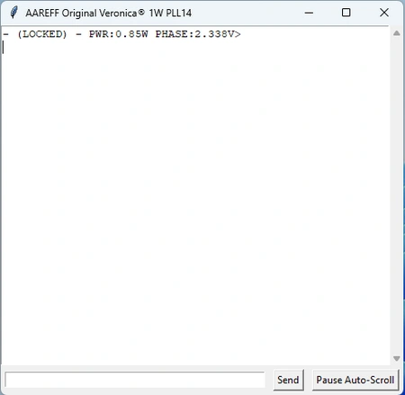
NEstado normal cuando el dispositivo está conectado: el PLL está BLOQUEADO con una potencia de salida de 0.85W y una fase PLL de 2.33V
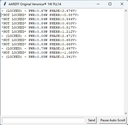
Esto muestra lo que sucede si el dispositivo pierde su bloqueo. Simulamos una falla colocando nuestros dedos en las bobinas del oscilador.
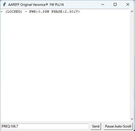
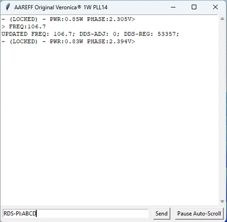
Esto muestra el regreso a la normalidad con el comando del usuario FREQ:106.7 escrito en el cuadro de entrada a continuación. Se puede establecer un valor entre 87.5 y 108.0 MHz.
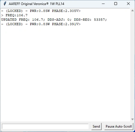
Después de presionar 'Enviar:', la pantalla muestra FRECUENCIA ACTUALIZADA 106.7 junto con otra información técnica. Esto hace que el transmisor cambie de frecuencia.
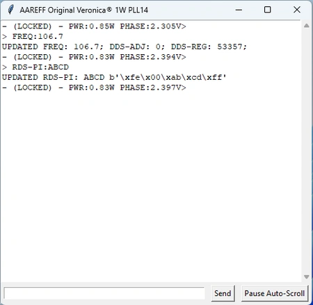
Esto muestra otro comando, RDS-PI:ABCD escrito para dispositivos con la tarjeta RDS.
Después de presionar 'Enviar:', la pantalla muestra RDS-PI ACTUALIZADO: ABCD actualizando instantáneamente el código PI de RDS.
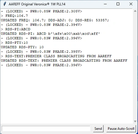
Esto muestra dos ejemplos adicionales de comandos RDS:
RDS-TEXT:[escribe tu mensaje aquí]
RDS-PTY:[número de 0 a 31]
El texto es ASCII simple de hasta 60 caracteres y los códigos PTY válidos se muestran a continuación.
A continuación, se muestran los comandos disponibles para el control de PC por USB, así como los códigos PTY para el tipo de programa. Seguiremos desarrollando mejoras y agregando más comandos útiles a esta aplicación en el futuro. Sigue consultando esta página para más detalles.
◼ DEVICE-ID
◼ STATUS
◼ FREQ:[87.5 a 108.0]
◼ DDS-ADJ:[-1,0 o 1]
◼ PWR:[0 a 1]
◼ RDS-PTY: [0 a 31 lista de códigos PTY]
◼ RDS-PI: [0000 a FFFF]
◼ RDS-TEXT:[hasta 60 caracteres.]
◼ RDS-ON
◼ RDS-OFF
Comandos adicionales tras la actualización de firmware de octubre de 2025
◼ RDS-PS:[Cualquier string de hasta 8 caracteres.]
◼ RDS-MS:[0 o 1]
◼ RDS-TP:[0 o 1]
◼ RDS-TA:[0 o 1]
◼ RDS-AFNUM:[0 a 15]
◼ RDS-AF:[Hasta 15 freq. con formato, por ejemplo: 88.1, 88.7, 94.8]
◼ RDS-DI:[Entero de 0 a 31]
◼ RDS-RT:[Cualquier string de hasta 60 caracteres.]
◼ RDS-SCROLL:[0 o 1]
USB PC/RDS CONTROL
Download our free PC app that connects 'plug and play' to the transmitter / PLL DDS exciter via USB. You can see the PLL status and change the frequency and power directly from the PC interface. If you choose to add the optional RDS card, you can also change the PI, PTY and scrolling text of the radio from the interface.
Below are the download links for Windows:
https://www.aareff.com/1wpllm/pll14.4/pll14.exe
https://www.aareff.com/1wpllm/pll14.4/pll14.zip
By clicking on these links, Windows may show you a warning that the software is from an unknown publisher. We assure you that we wrote the apps and the files are perfectly safe, virus-free and come from our registered domain www.aareff.com, which you can verify at https://lookup.icann.org/en/lookup
Normal state when the device is connected: the PLL is LOCKED with an output power of 0.85W and a PLL phase of 2.33V
This shows what happens if the device loses its lock. We simulated a failure by placing our fingers on the oscillator coils.
This shows the return to normal with the user command FREQ:106.7 typed in the input box below. A value between 87.5 and 108.0 MHz can be set.
After pressing 'Send:' the display returns UPDATED FREQ 106.7 along with other technical information. This causes the transmitter to change frequency.
This shows another command, RDS-PI:ABCD typed for devices with the RDS card.
After pressing 'Send': the display returns UPDATED RDS-PI:ABCD instantly updating the RDS PI code.
This shows two additional examples of RDS commands:
RDS-TEXT:[write your message here]
RDS-PTY:[number from 0 to 31]
Text is plain ASCII up to 60 chars and valid PTY Codes shown below.
Shown below are the current commands available for USB PC Control and also the PTY codes for program type. We will be making further developments, improvements and more useful commands to this app in the near future. Keep checking this page for details.
◼ DEVICE-ID
◼ STATUS
◼ FREQ:[87.5 to 108.0]
◼ DDS-ADJ:[-1,0 or 1]
◼ PWR:[0 to 1]
◼ RDS-PTY: [0 to 31 list of PTY codes]
◼ RDS-PI: [0000 to FFFF]
◼ RDS-TEXT:[any string up to 60 chars.]
◼ RDS-ON
◼ RDS-OFF
Additional commands following Oct 2025 firmware update
◼ RDS-PS:[any string up to 8 chars.]
◼ RDS-MS:[0 or 1]
◼ RDS-TP:[0 or 1]
◼ RDS-TA:[0 or 1]
◼ RDS-AFNUM:[0 to 15]
◼ RDS-AF:[Up to 15 freq. formatted eg. 88.1, 88.7, 94.8]
◼ RDS-DI:[0 to 31 integer]
◼ RDS-RT:[any string up to 60 chars.]
◼ RDS-SCROLL:[0 or 1]
MAINTENANCE
The only maintenance the amplifier needs is some periodic cleaning. Following a number of weeks of continuous 24/7 use (specified below), the transmitter should be shut down and disconnected. A technician or engineer needs to take of the top lid of the 30WNTA amplifier only by removing the 8 self tapper screws located on the top and 1 self tapper from the top of the front panel, Using a soft new and clean paint brush with a vacuum clean hose the dust should be gently brushed and sucked away from all areas inside. Pay particular attention to the fan at the front and the fan vents at rear.
| WEEKS | SALTY | SANDY | DUSTY | PUBLIC | CLEAN |
| 4 |  |
||||
| 6 | |
|
|||
| 8 | |
||||
| 12 | |
Do not adjust any factory set internal controls.
Under NO CIRCUMSTANCES should any adjustments be made to the internal controls. Such adjustments could damage the unit and invalidate the warranty and also cause serious interference to other users of the electromagnetic spectrum.
TECHNICAL DATA
(All stated measurements were made at 220VAC at 26 Degrees Celsius ambient temperature unless stated)
RF and AF Parameters
| Power Output Adj. | Adj. 1-30 Watts into 50 ohms |
| Freq Range | 87.5 to 108 MHz |
| Spurious Emissions | Less than -75 dB ref to carrier |
| Harmonic Emissions | Less than -70 dB ref to carrier |
| Out of Lock RF Muting | Less than -70 dB ref to carrier |
| Freq Stability | Less than +/- 2 KHz between -20 and +40 C |
| Freq Fine | Adj +/- 1000 Hz |
| Freq Adj. Accuracy | +/- 50 Hz |
| Deviation Sensitivity Stability | +/-2 % max |
| Residual AM | Less than 0.5 % |
| Synchronous AM | Less than 0.5 % |
| RF Output Connector | N type Female (or optional SO239/Female UHF) |
| RF Ruggedness | Any VSWR, phase, length of time |
| MPX Audio Input | Connector Phono/ RCA type unbalanced |
| Pre-emphasis | (50uS/ 75uS/ None) |
| MPX Audio Input Sensitivity | Nom. 0.775 V rms for +/- 75 KHz Dev. User adj. |
| MPX Signal To Noise Ratio | More than 72 dB rel. +/-75KHz dev. |
| MPX Audio Freq Response | Less than +/-0.5dB between 30 Hz and 76 KHz |
| MPX Audio Distortion | Less than 0.2 % THD |
| Operating Temp | -20 to +40 Deg C |
AC Power Supply
| Model | Meanwell GS90A15 |
| Input Voltage | 90 ~ 264VAC 127 ~ 370VDC |
| Input Power | 50-60W input for 30W RF OUT with RF SWR < 1.5 |
| Working Humidity | 20 ~ 90% RH non-condensing |
| Safety Standards | UL60950-1, TUV EN60950-1, BSMI CNS14336, CCC GB4943, J60950-1 I/PO/P: 3KVAC I/P-FG:2KVAC O/P-FG:0.5KVAC |
| EMC Conduction & Radiation | Compliance to EN55022 class B, EN61000-3-2,3, FCC PART 15 / CISPR22 class B, CNS13438 class B, GB9254, GB17625.1 |
| EMC Immunity | Compliance to EN61000-4-2,3,4,5,6,8,11, light industry level, criteria A |
DIL SWITCH (S2 and S1)
| MHz | 1 | 2 | 3 | 4 | 5 | 6 | 1 | 2 | 3 | 4 | 5 | 6 | |
|---|---|---|---|---|---|---|---|---|---|---|---|---|---|
| 87.5 | ON | ON | OFF | OFF | ON | OFF | OFF | ON | OFF | ON | OFF | ON | |
| 87.6 | ON | ON | OFF | OFF | ON | OFF | OFF | ON | OFF | ON | OFF | OFF | |
| 87.7 | ON | ON | OFF | OFF | ON | OFF | OFF | ON | OFF | OFF | ON | ON | |
| 87.8 | ON | ON | OFF | OFF | ON | OFF | OFF | ON | OFF | OFF | ON | OFF | |
| 87.9 | ON | ON | OFF | OFF | ON | OFF | OFF | ON | OFF | OFF | OFF | ON | |
| 88 | ON | ON | OFF | OFF | ON | OFF | OFF | ON | OFF | OFF | OFF | OFF | |
| 88.1 | ON | ON | OFF | OFF | ON | OFF | OFF | OFF | ON | ON | ON | ON | |
| 88.2 | ON | ON | OFF | OFF | ON | OFF | OFF | OFF | ON | ON | ON | OFF | |
| 88.3 | ON | ON | OFF | OFF | ON | OFF | OFF | OFF | ON | ON | OFF | ON | |
| 88.4 | ON | ON | OFF | OFF | ON | OFF | OFF | OFF | ON | ON | OFF | OFF | |
| 88.5 | ON | ON | OFF | OFF | ON | OFF | OFF | OFF | ON | OFF | ON | ON | |
| 88.6 | ON | ON | OFF | OFF | ON | OFF | OFF | OFF | ON | OFF | ON | OFF | |
| 88.7 | ON | ON | OFF | OFF | ON | OFF | OFF | OFF | ON | OFF | OFF | ON | |
| 88.8 | ON | ON | OFF | OFF | ON | OFF | OFF | OFF | ON | OFF | OFF | OFF | |
| 88.9 | ON | ON | OFF | OFF | ON | OFF | OFF | OFF | OFF | ON | ON | ON | |
| 89 | ON | ON | OFF | OFF | ON | OFF | OFF | OFF | OFF | ON | ON | OFF | |
| 89.1 | ON | ON | OFF | OFF | ON | OFF | OFF | OFF | OFF | ON | OFF | ON | |
| 89.2 | ON | ON | OFF | OFF | ON | OFF | OFF | OFF | OFF | ON | OFF | OFF | |
| 89.3 | ON | ON | OFF | OFF | ON | OFF | OFF | OFF | OFF | OFF | ON | ON | |
| 89.4 | ON | ON | OFF | OFF | ON | OFF | OFF | OFF | OFF | OFF | ON | OFF | |
| 89.5 | ON | ON | OFF | OFF | ON | OFF | OFF | OFF | OFF | OFF | OFF | ON | |
| 89.6 | ON | ON | OFF | OFF | ON | OFF | OFF | OFF | OFF | OFF | OFF | OFF | |
| 89.7 | ON | ON | OFF | OFF | OFF | ON | ON | ON | ON | ON | ON | ON | |
| 89.8 | ON | ON | OFF | OFF | OFF | ON | ON | ON | ON | ON | ON | OFF | |
| 89.9 | ON | ON | OFF | OFF | OFF | ON | ON | ON | ON | ON | OFF | ON | |
| 90 | ON | ON | OFF | OFF | OFF | ON | ON | ON | ON | ON | OFF | OFF | |
| 90.1 | ON | ON | OFF | OFF | OFF | ON | ON | ON | ON | OFF | ON | ON | |
| 90.2 | ON | ON | OFF | OFF | OFF | ON | ON | ON | ON | OFF | ON | OFF | |
| 90.3 | ON | ON | OFF | OFF | OFF | ON | ON | ON | ON | OFF | OFF | ON | |
| 90.4 | ON | ON | OFF | OFF | OFF | ON | ON | ON | ON | OFF | OFF | OFF | |
| 90.5 | ON | ON | OFF | OFF | OFF | ON | ON | ON | OFF | ON | ON | ON | |
| 90.6 | ON | ON | OFF | OFF | OFF | ON | ON | ON | OFF | ON | ON | OFF | |
| 90.7 | ON | ON | OFF | OFF | OFF | ON | ON | ON | OFF | ON | OFF | ON | |
| 90.8 | ON | ON | OFF | OFF | OFF | ON | ON | ON | OFF | ON | OFF | OFF | |
| 90.9 | ON | ON | OFF | OFF | OFF | ON | ON | ON | OFF | OFF | ON | ON | |
| 91 | ON | ON | OFF | OFF | OFF | ON | ON | ON | OFF | OFF | ON | OFF | |
| 91.1 | ON | ON | OFF | OFF | OFF | ON | ON | ON | OFF | OFF | OFF | ON | |
| 91.2 | ON | ON | OFF | OFF | OFF | ON | ON | ON | OFF | OFF | OFF | OFF | |
| 91.3 | ON | ON | OFF | OFF | OFF | ON | ON | OFF | ON | ON | ON | ON | |
| 91.4 | ON | ON | OFF | OFF | OFF | ON | ON | OFF | ON | ON | ON | OFF | |
| 91.5 | ON | ON | OFF | OFF | OFF | ON | ON | OFF | ON | ON | OFF | ON | |
| 91.6 | ON | ON | OFF | OFF | OFF | ON | ON | OFF | ON | ON | OFF | OFF | |
| 91.7 | ON | ON | OFF | OFF | OFF | ON | ON | OFF | ON | OFF | ON | ON | |
| 91.8 | ON | ON | OFF | OFF | OFF | ON | ON | OFF | ON | OFF | ON | OFF | |
| 91.9 | ON | ON | OFF | OFF | OFF | ON | ON | OFF | ON | OFF | OFF | ON | |
| 92 | ON | ON | OFF | OFF | OFF | ON | ON | OFF | ON | OFF | OFF | OFF | |
| 92.1 | ON | ON | OFF | OFF | OFF | ON | ON | OFF | OFF | ON | ON | ON | |
| 92.2 | ON | ON | OFF | OFF | OFF | ON | ON | OFF | OFF | ON | ON | OFF | |
| 92.3 | ON | ON | OFF | OFF | OFF | ON | ON | OFF | OFF | ON | OFF | ON | |
| 92.4 | ON | ON | OFF | OFF | OFF | ON | ON | OFF | OFF | ON | OFF | OFF | |
| 92.5 | ON | ON | OFF | OFF | OFF | ON | ON | OFF | OFF | OFF | ON | ON | |
| 92.6 | ON | ON | OFF | OFF | OFF | ON | ON | OFF | OFF | OFF | ON | OFF | |
| 92.7 | ON | ON | OFF | OFF | OFF | ON | ON | OFF | OFF | OFF | OFF | ON | |
| 92.8 | ON | ON | OFF | OFF | OFF | ON | ON | OFF | OFF | OFF | OFF | OFF | |
| 92.9 | ON | ON | OFF | OFF | OFF | ON | OFF | ON | ON | ON | ON | ON | |
| 93 | ON | ON | OFF | OFF | OFF | ON | OFF | ON | ON | ON | ON | OFF | |
| 93.1 | ON | ON | OFF | OFF | OFF | ON | OFF | ON | ON | ON | OFF | ON | |
| 93.2 | ON | ON | OFF | OFF | OFF | ON | OFF | ON | ON | ON | OFF | OFF | |
| 93.3 | ON | ON | OFF | OFF | OFF | ON | OFF | ON | ON | OFF | ON | ON | |
| 93.4 | ON | ON | OFF | OFF | OFF | ON | OFF | ON | ON | OFF | ON | OFF | |
| 93.5 | ON | ON | OFF | OFF | OFF | ON | OFF | ON | ON | OFF | OFF | ON | |
| 93.6 | ON | ON | OFF | OFF | OFF | ON | OFF | ON | ON | OFF | OFF | OFF | |
| 93.7 | ON | ON | OFF | OFF | OFF | ON | OFF | ON | OFF | ON | ON | ON | |
| 93.8 | ON | ON | OFF | OFF | OFF | ON | OFF | ON | OFF | ON | ON | OFF | |
| 93.9 | ON | ON | OFF | OFF | OFF | ON | OFF | ON | OFF | ON | OFF | ON | |
| 94 | ON | ON | OFF | OFF | OFF | ON | OFF | ON | OFF | ON | OFF | OFF | |
| 94.1 | ON | ON | OFF | OFF | OFF | ON | OFF | ON | OFF | OFF | ON | ON | |
| 94.2 | ON | ON | OFF | OFF | OFF | ON | OFF | ON | OFF | OFF | ON | OFF | |
| 94.3 | ON | ON | OFF | OFF | OFF | ON | OFF | ON | OFF | OFF | OFF | ON | |
| 94.4 | ON | ON | OFF | OFF | OFF | ON | OFF | ON | OFF | OFF | OFF | OFF | |
| 94.5 | ON | ON | OFF | OFF | OFF | ON | OFF | OFF | ON | ON | ON | ON | |
| 94.6 | ON | ON | OFF | OFF | OFF | ON | OFF | OFF | ON | ON | ON | OFF | |
| 94.7 | ON | ON | OFF | OFF | OFF | ON | OFF | OFF | ON | ON | OFF | ON | |
| 94.8 | ON | ON | OFF | OFF | OFF | ON | OFF | OFF | ON | ON | OFF | OFF | |
| 94.9 | ON | ON | OFF | OFF | OFF | ON | OFF | OFF | ON | OFF | ON | ON | |
| 95 | ON | ON | OFF | OFF | OFF | ON | OFF | OFF | ON | OFF | ON | OFF | |
| 95.1 | ON | ON | OFF | OFF | OFF | ON | OFF | OFF | ON | OFF | OFF | ON | |
| 95.2 | ON | ON | OFF | OFF | OFF | ON | OFF | OFF | ON | OFF | OFF | OFF | |
| 95.3 | ON | ON | OFF | OFF | OFF | ON | OFF | OFF | OFF | ON | ON | ON | |
| 95.4 | ON | ON | OFF | OFF | OFF | ON | OFF | OFF | OFF | ON | ON | OFF | |
| 95.5 | ON | ON | OFF | OFF | OFF | ON | OFF | OFF | OFF | ON | OFF | ON | |
| 95.6 | ON | ON | OFF | OFF | OFF | ON | OFF | OFF | OFF | ON | OFF | OFF | |
| 95.7 | ON | ON | OFF | OFF | OFF | ON | OFF | OFF | OFF | OFF | ON | ON | |
| 95.8 | ON | ON | OFF | OFF | OFF | ON | OFF | OFF | OFF | OFF | ON | OFF | |
| 95.9 | ON | ON | OFF | OFF | OFF | ON | OFF | OFF | OFF | OFF | OFF | ON | |
| 96 | ON | ON | OFF | OFF | OFF | ON | OFF | OFF | OFF | OFF | OFF | OFF | |
| 96.1 | ON | ON | OFF | OFF | OFF | OFF | ON | ON | ON | ON | ON | ON | |
| 96.2 | ON | ON | OFF | OFF | OFF | OFF | ON | ON | ON | ON | ON | OFF | |
| 96.3 | ON | ON | OFF | OFF | OFF | OFF | ON | ON | ON | ON | OFF | ON | |
| 96.4 | ON | ON | OFF | OFF | OFF | OFF | ON | ON | ON | ON | OFF | OFF | |
| 96.5 | ON | ON | OFF | OFF | OFF | OFF | ON | ON | ON | OFF | ON | ON | |
| 96.6 | ON | ON | OFF | OFF | OFF | OFF | ON | ON | ON | OFF | ON | OFF | |
| 96.7 | ON | ON | OFF | OFF | OFF | OFF | ON | ON | ON | OFF | OFF | ON | |
| 96.8 | ON | ON | OFF | OFF | OFF | OFF | ON | ON | ON | OFF | OFF | OFF | |
| 96.9 | ON | ON | OFF | OFF | OFF | OFF | ON | ON | OFF | ON | ON | ON | |
| 97 | ON | ON | OFF | OFF | OFF | OFF | ON | ON | OFF | ON | ON | OFF | |
| 97.1 | ON | ON | OFF | OFF | OFF | OFF | ON | ON | OFF | ON | OFF | ON | |
| 97.2 | ON | ON | OFF | OFF | OFF | OFF | ON | ON | OFF | ON | OFF | OFF | |
| 97.3 | ON | ON | OFF | OFF | OFF | OFF | ON | ON | OFF | OFF | ON | ON | |
| 97.4 | ON | ON | OFF | OFF | OFF | OFF | ON | ON | OFF | OFF | ON | OFF | |
| 97.5 | ON | ON | OFF | OFF | OFF | OFF | ON | ON | OFF | OFF | OFF | ON | |
| 97.6 | ON | ON | OFF | OFF | OFF | OFF | ON | ON | OFF | OFF | OFF | OFF | |
| 97.7 | ON | ON | OFF | OFF | OFF | OFF | ON | OFF | ON | ON | ON | ON | |
| 97.8 | ON | ON | OFF | OFF | OFF | OFF | ON | OFF | ON | ON | ON | OFF | |
| 97.9 | ON | ON | OFF | OFF | OFF | OFF | ON | OFF | ON | ON | OFF | ON | |
| 98 | ON | ON | OFF | OFF | OFF | OFF | ON | OFF | ON | ON | OFF | OFF | |
| 98.1 | ON | ON | OFF | OFF | OFF | OFF | ON | OFF | ON | OFF | ON | ON | |
| 98.2 | ON | ON | OFF | OFF | OFF | OFF | ON | OFF | ON | OFF | ON | OFF | |
| 98.3 | ON | ON | OFF | OFF | OFF | OFF | ON | OFF | ON | OFF | OFF | ON | |
| 98.4 | ON | ON | OFF | OFF | OFF | OFF | ON | OFF | ON | OFF | OFF | OFF | |
| 98.5 | ON | ON | OFF | OFF | OFF | OFF | ON | OFF | OFF | ON | ON | ON | |
| 98.6 | ON | ON | OFF | OFF | OFF | OFF | ON | OFF | OFF | ON | ON | OFF | |
| 98.7 | ON | ON | OFF | OFF | OFF | OFF | ON | OFF | OFF | ON | OFF | ON | |
| 98.8 | ON | ON | OFF | OFF | OFF | OFF | ON | OFF | OFF | ON | OFF | OFF | |
| 98.9 | ON | ON | OFF | OFF | OFF | OFF | ON | OFF | OFF | OFF | ON | ON | |
| 99 | ON | ON | OFF | OFF | OFF | OFF | ON | OFF | OFF | OFF | ON | OFF | |
| 99.1 | ON | ON | OFF | OFF | OFF | OFF | ON | OFF | OFF | OFF | OFF | ON | |
| 99.2 | ON | ON | OFF | OFF | OFF | OFF | ON | OFF | OFF | OFF | OFF | OFF | |
| 99.3 | ON | ON | OFF | OFF | OFF | OFF | OFF | ON | ON | ON | ON | ON | |
| 99.4 | ON | ON | OFF | OFF | OFF | OFF | OFF | ON | ON | ON | ON | OFF | |
| 99.5 | ON | ON | OFF | OFF | OFF | OFF | OFF | ON | ON | ON | OFF | ON | |
| 99.6 | ON | ON | OFF | OFF | OFF | OFF | OFF | ON | ON | ON | OFF | OFF | |
| 99.7 | ON | ON | OFF | OFF | OFF | OFF | OFF | ON | ON | OFF | ON | ON | |
| 99.8 | ON | ON | OFF | OFF | OFF | OFF | OFF | ON | ON | OFF | ON | OFF | |
| 99.9 | ON | ON | OFF | OFF | OFF | OFF | OFF | ON | ON | OFF | OFF | ON | |
| 100 | ON | ON | OFF | OFF | OFF | OFF | OFF | ON | ON | OFF | OFF | OFF | |
| 100.1 | ON | ON | OFF | OFF | OFF | OFF | OFF | ON | OFF | ON | ON | ON | |
| 100.2 | ON | ON | OFF | OFF | OFF | OFF | OFF | ON | OFF | ON | ON | OFF | |
| 100.3 | ON | ON | OFF | OFF | OFF | OFF | OFF | ON | OFF | ON | OFF | ON | |
| 100.4 | ON | ON | OFF | OFF | OFF | OFF | OFF | ON | OFF | ON | OFF | OFF | |
| 100.5 | ON | ON | OFF | OFF | OFF | OFF | OFF | ON | OFF | OFF | ON | ON | |
| 100.6 | ON | ON | OFF | OFF | OFF | OFF | OFF | ON | OFF | OFF | ON | OFF | |
| 100.7 | ON | ON | OFF | OFF | OFF | OFF | OFF | ON | OFF | OFF | OFF | ON | |
| 100.8 | ON | ON | OFF | OFF | OFF | OFF | OFF | ON | OFF | OFF | OFF | OFF | |
| 100.9 | ON | ON | OFF | OFF | OFF | OFF | OFF | OFF | ON | ON | ON | ON | |
| 101 | ON | ON | OFF | OFF | OFF | OFF | OFF | OFF | ON | ON | ON | OFF | |
| 101.1 | ON | ON | OFF | OFF | OFF | OFF | OFF | OFF | ON | ON | OFF | ON | |
| 101.2 | ON | ON | OFF | OFF | OFF | OFF | OFF | OFF | ON | ON | OFF | OFF | |
| 101.3 | ON | ON | OFF | OFF | OFF | OFF | OFF | OFF | ON | OFF | ON | ON | |
| 101.4 | ON | ON | OFF | OFF | OFF | OFF | OFF | OFF | ON | OFF | ON | OFF | |
| 101.5 | ON | ON | OFF | OFF | OFF | OFF | OFF | OFF | ON | OFF | OFF | ON | |
| 101.6 | ON | ON | OFF | OFF | OFF | OFF | OFF | OFF | ON | OFF | OFF | OFF | |
| 101.7 | ON | ON | OFF | OFF | OFF | OFF | OFF | OFF | OFF | ON | ON | ON | |
| 101.8 | ON | ON | OFF | OFF | OFF | OFF | OFF | OFF | OFF | ON | ON | OFF | |
| 101.9 | ON | ON | OFF | OFF | OFF | OFF | OFF | OFF | OFF | ON | OFF | ON | |
| 102 | ON | ON | OFF | OFF | OFF | OFF | OFF | OFF | OFF | ON | OFF | OFF | |
| 102.1 | ON | ON | OFF | OFF | OFF | OFF | OFF | OFF | OFF | OFF | ON | ON | |
| 102.2 | ON | ON | OFF | OFF | OFF | OFF | OFF | OFF | OFF | OFF | ON | OFF | |
| 102.3 | ON | ON | OFF | OFF | OFF | OFF | OFF | OFF | OFF | OFF | OFF | ON | |
| 102.4 | ON | ON | OFF | OFF | OFF | OFF | OFF | OFF | OFF | OFF | OFF | OFF | |
| 102.5 | ON | OFF | ON | ON | ON | ON | ON | ON | ON | ON | ON | ON | |
| 102.6 | ON | OFF | ON | ON | ON | ON | ON | ON | ON | ON | ON | OFF | |
| 102.7 | ON | OFF | ON | ON | ON | ON | ON | ON | ON | ON | OFF | ON | |
| 102.8 | ON | OFF | ON | ON | ON | ON | ON | ON | ON | ON | OFF | OFF | |
| 102.9 | ON | OFF | ON | ON | ON | ON | ON | ON | ON | OFF | ON | ON | |
| 103 | ON | OFF | ON | ON | ON | ON | ON | ON | ON | OFF | ON | OFF | |
| 103.1 | ON | OFF | ON | ON | ON | ON | ON | ON | ON | OFF | OFF | ON | |
| 103.2 | ON | OFF | ON | ON | ON | ON | ON | ON | ON | OFF | OFF | OFF | |
| 103.3 | ON | OFF | ON | ON | ON | ON | ON | ON | OFF | ON | ON | ON | |
| 103.4 | ON | OFF | ON | ON | ON | ON | ON | ON | OFF | ON | ON | OFF | |
| 103.5 | ON | OFF | ON | ON | ON | ON | ON | ON | OFF | ON | OFF | ON | |
| 103.6 | ON | OFF | ON | ON | ON | ON | ON | ON | OFF | ON | OFF | OFF | |
| 103.7 | ON | OFF | ON | ON | ON | ON | ON | ON | OFF | OFF | ON | ON | |
| 103.8 | ON | OFF | ON | ON | ON | ON | ON | ON | OFF | OFF | ON | OFF | |
| 103.9 | ON | OFF | ON | ON | ON | ON | ON | ON | OFF | OFF | OFF | ON | |
| 104 | ON | OFF | ON | ON | ON | ON | ON | ON | OFF | OFF | OFF | OFF | |
| 104.1 | ON | OFF | ON | ON | ON | ON | ON | OFF | ON | ON | ON | ON | |
| 104.2 | ON | OFF | ON | ON | ON | ON | ON | OFF | ON | ON | ON | OFF | |
| 104.3 | ON | OFF | ON | ON | ON | ON | ON | OFF | ON | ON | OFF | ON | |
| 104.4 | ON | OFF | ON | ON | ON | ON | ON | OFF | ON | ON | OFF | OFF | |
| 104.5 | ON | OFF | ON | ON | ON | ON | ON | OFF | ON | OFF | ON | ON | |
| 104.6 | ON | OFF | ON | ON | ON | ON | ON | OFF | ON | OFF | ON | OFF | |
| 104.7 | ON | OFF | ON | ON | ON | ON | ON | OFF | ON | OFF | OFF | ON | |
| 104.8 | ON | OFF | ON | ON | ON | ON | ON | OFF | ON | OFF | OFF | OFF | |
| 104.9 | ON | OFF | ON | ON | ON | ON | ON | OFF | OFF | ON | ON | ON | |
| 105 | ON | OFF | ON | ON | ON | ON | ON | OFF | OFF | ON | ON | OFF | |
| 105.1 | ON | OFF | ON | ON | ON | ON | ON | OFF | OFF | ON | OFF | ON | |
| 105.2 | ON | OFF | ON | ON | ON | ON | ON | OFF | OFF | ON | OFF | OFF | |
| 105.3 | ON | OFF | ON | ON | ON | ON | ON | OFF | OFF | OFF | ON | ON | |
| 105.4 | ON | OFF | ON | ON | ON | ON | ON | OFF | OFF | OFF | ON | OFF | |
| 105.5 | ON | OFF | ON | ON | ON | ON | ON | OFF | OFF | OFF | OFF | ON | |
| 105.6 | ON | OFF | ON | ON | ON | ON | ON | OFF | OFF | OFF | OFF | OFF | |
| 105.7 | ON | OFF | ON | ON | ON | ON | OFF | ON | ON | ON | ON | ON | |
| 105.8 | ON | OFF | ON | ON | ON | ON | OFF | ON | ON | ON | ON | OFF | |
| 105.9 | ON | OFF | ON | ON | ON | ON | OFF | ON | ON | ON | OFF | ON | |
| 106 | ON | OFF | ON | ON | ON | ON | OFF | ON | ON | ON | OFF | OFF | |
| 106.1 | ON | OFF | ON | ON | ON | ON | OFF | ON | ON | OFF | ON | ON | |
| 106.2 | ON | OFF | ON | ON | ON | ON | OFF | ON | ON | OFF | ON | OFF | |
| 106.3 | ON | OFF | ON | ON | ON | ON | OFF | ON | ON | OFF | OFF | ON | |
| 106.4 | ON | OFF | ON | ON | ON | ON | OFF | ON | ON | OFF | OFF | OFF | |
| 106.5 | ON | OFF | ON | ON | ON | ON | OFF | ON | OFF | ON | ON | ON | |
| 106.6 | ON | OFF | ON | ON | ON | ON | OFF | ON | OFF | ON | ON | OFF | |
| 106.7 | ON | OFF | ON | ON | ON | ON | OFF | ON | OFF | ON | OFF | ON | |
| 106.8 | ON | OFF | ON | ON | ON | ON | OFF | ON | OFF | ON | OFF | OFF | |
| 106.9 | ON | OFF | ON | ON | ON | ON | OFF | ON | OFF | OFF | ON | ON | |
| 107 | ON | OFF | ON | ON | ON | ON | OFF | ON | OFF | OFF | ON | OFF | |
| 107.1 | ON | OFF | ON | ON | ON | ON | OFF | ON | OFF | OFF | OFF | ON | |
| 107.2 | ON | OFF | ON | ON | ON | ON | OFF | ON | OFF | OFF | OFF | OFF | |
| 107.3 | ON | OFF | ON | ON | ON | ON | OFF | OFF | ON | ON | ON | ON | |
| 107.4 | ON | OFF | ON | ON | ON | ON | OFF | OFF | ON | ON | ON | OFF | |
| 107.5 | ON | OFF | ON | ON | ON | ON | OFF | OFF | ON | ON | OFF | ON | |
| 107.6 | ON | OFF | ON | ON | ON | ON | OFF | OFF | ON | ON | OFF | OFF | |
| 107.7 | ON | OFF | ON | ON | ON | ON | OFF | OFF | ON | OFF | ON | ON | |
| 107.8 | ON | OFF | ON | ON | ON | ON | OFF | OFF | ON | OFF | ON | OFF | |
| 107.9 | ON | OFF | ON | ON | ON | ON | OFF | OFF | ON | OFF | OFF | ON | |
| 108 | ON | OFF | ON | ON | ON | ON | OFF | OFF | ON | OFF | OFF | OFF |
DECLARATION OF CONFORMITY
AAREFF TRANSMISSION SYSTEMS SL
AVDA ANDALUCIA 1
LA ALFOQUIA-ZURGENA
04661
ALMERIA
ESPANA.
Paul Hollings
![]()
In Zurgena, Almería, Spain on 01 of November 2009, the equipment:
AAREFF 30 Watt Band II VHF FM Broadcasting Transmitter (30WPLL19, 30WPLLS19, 30WPLLSL19)
European Union
We verify and declare that this equipment meets the essential requirements of the R&TTE directive, EMC directive and the LVD by compliance with the following standards in the sections applicable.
- ETS 300384 or ETSI EN 302018-1 V1.2.1 (2005-12) when used with the audio compressor limiter included with the product.
- EN 301489-11 V1.3.1 (2006-05) EMC Electromagnetic Compatibility when used with one meter AC mains cord supplied. If the installation engineer needs to extend this cord, this and the audio input cable should be no more than 3 meters in length to remain in compliance with EMC directive.
- 2006/95/EC Directive (2006-12) LVD Low Voltage Directive.
Equipment compliance is possible using equipment from and in conjunction from other manufacturers, but since this is beyond the control of Aareff Systems, Aareff Systems cannot or be expected to guarantee compliance in this situation.
United States
We verify and declare that this equipment complies with the following list of FCC technical requirements. The equipment has not been independently tested by an FCC recognised listed laboratory and for this reason it is not certified, but it is verified.
47 CFR Chapter I Federal Communications Commission sections:
- 73.1560, 2.1046 RF Power
- 73.1545, 2.1055 Frequency Stability
- 73.317, 2.1049 (e)(3) Emission Limitation, Emission Mask
- 73.317, 2.1057, 2.1051 Emission Limits, Spurious Emissions at Antenna Terminal
- 73.317, 2.1057, 2.1053 Emission Limits, Field Strength of Spurious Emissions
ROHS
All components used in this apparatus are RoHS compliant and do not contain above the specified limits in any of the following restricted substances:
- Lead
- Hexavalent Chromium
- Mercury
- Cadmium
- Polybrominated Biphenyls (PBB's)
- Polybrominated Diphenylethers (PBDE's)
LEGAL ADVICE
We sell this equipment to professionals and organizations in good faith it will be used correctly and legally. Nearly every country in the world require licensing for this type of equipment. It is the customer’s responsibility to check relevant laws, directives, regulations and licensing requirements before installing or putting this product into service with an antenna system. You, the customer or user agree to defend, indemnify and hold harmless Aareff Systems Limited, it’s employees and agents, from and against any claims, actions or demands, including without limitation legal and accounting fees, alleging or resulting from improper or unlawful use of this equipment.
PRODUCT END OF LIFE
This apparatus must NOT be disposed of with other domestic waste.
We are fully committed to maintaining our responsibilities to the environment. Owners of apparatus that has reached the end of it's useful life can return it to us for recycling, recondition, reuse or proper disposal. You will be required to pay lowest cost postal service available to ship the apparatus to us. Before shipping please contact us for more important information.
NEED TO BUY ONE?
© 2019 AAREFF SYSTEMS LIMITED
ALL RIGHTS RESERVED. Aareff is a trademark of Aareff Transmission Systems. All contents of this document including, but not limited to the images, logos, text, illustrations are protected by copyrights, trademarks and other intellectual property rights which are owned and controlled by Aareff Transmission Systems or by other parties that have licensed their material to Aareff Transmission Systems. This document in part or whole may not be copied, reproduced, republished, uploaded, posted or distributed in any way, including by e-mail, ftp or any other electronic means
Every care has been taken in the preparation of this document, errors in content, typographical or otherwise, may have occurred. If you have comments concerning its accuracy, please contact Aareff Systems Limited (UK)