+1 829 698 0733
What Do You Need? Talk To Us
+1 829 698 0733
What Do You Need? Talk To Us
8am-4pm EST/NY Monday-Friday
info@aareff.com 
5 GHz Digital Broadcast Low Latency Studio to Transmitter Link (STL)
- ULTRA-LOW LATENCY, LESS THAN 0.5S
- 15 km / 24 km LINE OF SIGHT
- 23 dBi / 29 dBi ANTENNAS
- 30 m / 60 m SHIELDED PoE CAT6A CABLES
- BUILT-IN BACKUP AoIP OVER VPN
- ADVANCED REMOTE GRAPHICAL DASHBOARD
- BUILT-IN HLS STREAMING & REMOTE ACCESS
- HEAVY-DUTY 2U 19″ POWDER-COATED STEEL CHASSIS

|
5 YEARS
LIMITED WARRANTY
|
Everything Included and Ready to Operate on Delivery
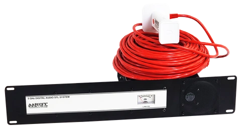
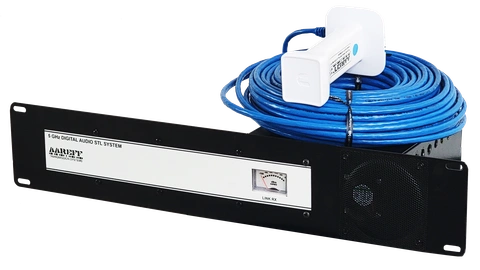
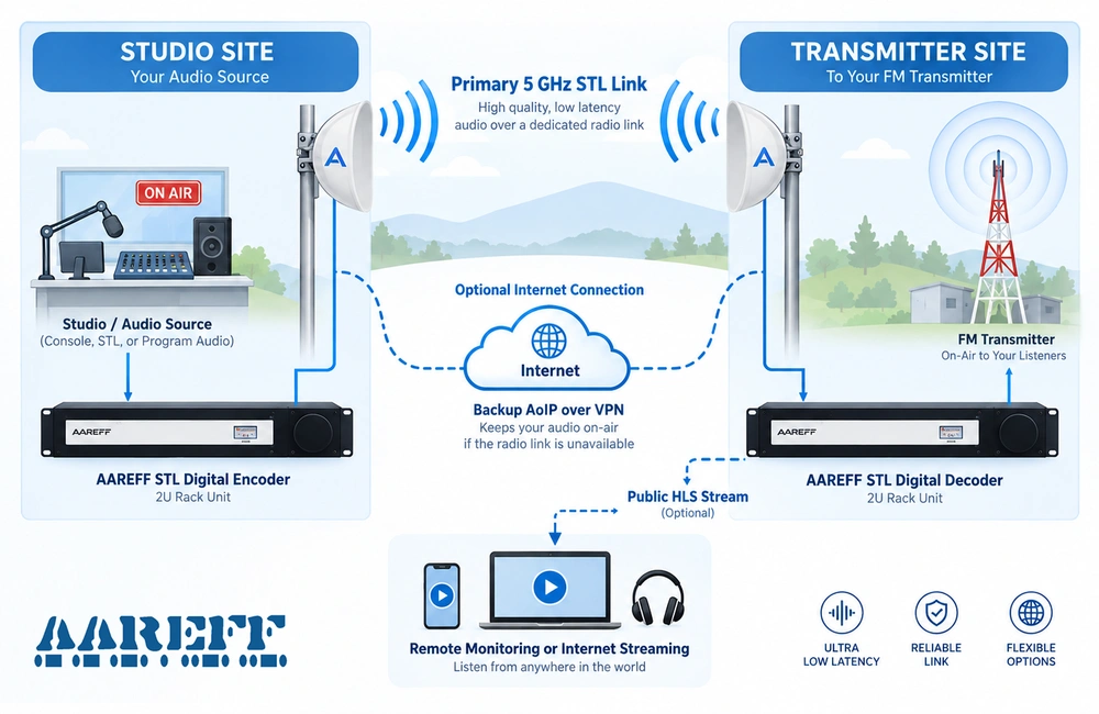
Connect the supplied 19 inch 2U encoder and decoder shown above, the red and blue PoE cables, and the active antennas. Connect to your studio console or audio processor using the standard XLR audio connections and power up the units from any 90–260 V AC supply. Point the antennas towards each other and the STL link will connect and start transferring audio automatically after about 40 seconds. Everything is supplied and factory configured for normal operation.
For short links up to a few hundred metres, the active antennas can be used directly. For long-range links up to 15 km or 24 km, fit the supplied parabolic antenna hardware to the active antennas and mount them on suitable towers or masts with clear line of sight.
Advanced Technology, Simple Installation, Long-Term Reliability
Designed by an experienced ex-BBC broadcast engineer for broadcasters who need a complete system that is easy to install, dependable for continuous 24/7 operation and protected by a 5-year warranty.

COMPLETE SYSTEM
Encoder, decoder, antennas and cabling all included providing a complete working system
EASY TO INSTALL
Factory configured and extensively soak-tested before delivery.
RELIABLE 24/7 LINK
Dedicated 5 GHz radio link designed for continuous broadcast operation.

5-YEAR WARRANTY
Professional equipment backed by long-term protection and experienced technical support.
Technical Overview
For engineers and technical advisers, the sections below provide a closer look at the STL's low-latency audio, 5 GHz RF link, hardware and installation, backup systems, remote dashboard and streaming capabilities. Expand any of the sections below for more technical information.
 Ultra-Low Latency Audio
High-quality Opus audio over RTP/UDP with less than 0.5 s end-to-end latency.
Dedicated low-latency transport for live studio-to-transmitter operation.
Ultra-Low Latency Audio
High-quality Opus audio over RTP/UDP with less than 0.5 s end-to-end latency.
Dedicated low-latency transport for live studio-to-transmitter operation.
The STL uses high-quality Opus audio encoding carried directly over RTP/UDP, providing efficient broadcast-quality audio with very low delay. Typical end-to-end latency is less than 0.5 seconds, making the link suitable for live studio monitoring and normal broadcast operation.
Unlike conventional internet streaming systems, the primary audio path operates across the dedicated 5 GHz radio link and does not depend on the public internet.
 5 GHz RF Link
15 km / 24 km point-to-point link using 23 dBi / 29 dBi antennas.
Dedicated 5 GHz radio path designed for permanent line-of-sight broadcast use.
5 GHz RF Link
15 km / 24 km point-to-point link using 23 dBi / 29 dBi antennas.
Dedicated 5 GHz radio path designed for permanent line-of-sight broadcast use.
The STL uses a dedicated 5 GHz point-to-point radio link between the studio and transmitter site, with antenna options designed for approximately 15 km or 24 km line-of-sight paths.
High-gain 23 dBi and 29 dBi directional antennas concentrate the radio signal toward the remote site, providing a dedicated wireless path for permanent studio-to-transmitter operation.
 Hardware & Installation
Heavy-duty 2U 19-inch rack hardware with 30 m / 60 m shielded PoE CAT6A cabling.
Supplied pre-configured to simplify installation and reduce setup time on site.
Hardware & Installation
Heavy-duty 2U 19-inch rack hardware with 30 m / 60 m shielded PoE CAT6A cabling.
Supplied pre-configured to simplify installation and reduce setup time on site.
The STL system is supplied in professional heavy-duty 2U 19-inch rack-mount steel chassis, designed for dependable fixed installation in studio and transmitter-site environments.
Shielded PoE CAT6A cabling is included for the outdoor radio units, with 30 m or 60 m cable lengths depending on the system selected. Power and network data are carried through the same cable, and the complete system is pre-configured before delivery to make installation faster and more straightforward.
 Backup & Redundancy
Built-in AoIP backup over VPN provides an alternative path if the primary 5 GHz link is unavailable.
Helps maintain continuous program audio during temporary radio-link interruptions.
Backup & Redundancy
Built-in AoIP backup over VPN provides an alternative path if the primary 5 GHz link is unavailable.
Helps maintain continuous program audio during temporary radio-link interruptions.
The STL includes a backup Audio-over-IP path using the internet and VPN, providing an alternative route between the studio and transmitter site if the primary 5 GHz radio link is temporarily unavailable.
This additional path is designed to improve operational resilience and reduce the risk of an off-air condition caused by a temporary failure or interruption of the main radio link.
 Remote Dashboard & Control
Advanced remote graphical dashboard for monitoring and control of the STL link.
Check system status, supervise operation and manage the link more easily.
Remote Dashboard & Control
Advanced remote graphical dashboard for monitoring and control of the STL link.
Check system status, supervise operation and manage the link more easily.
The system includes an advanced remote graphical dashboard that gives the operator a practical overview of the STL installation and its operating condition.
The dashboard provides convenient access to system status and operational information, making day-to-day supervision and remote management of the link easier.
 Streaming & Remote Access
Built-in HLS streaming capability provides optional remote listening from other locations.
Useful for supervision, confidence monitoring and convenient off-site access.
Streaming & Remote Access
Built-in HLS streaming capability provides optional remote listening from other locations.
Useful for supervision, confidence monitoring and convenient off-site access.
The system includes HLS streaming capability, allowing the program audio to be made available over the internet for remote listening and monitoring when required.
This provides flexible access for confidence monitoring, off-site supervision and convenient remote listening without affecting the primary dedicated 5 GHz STL path.
USER MANUAL (15km Version)
PACKAGE CONTENTS CHECKLIST
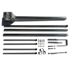
| 2 x Center reflector panel |
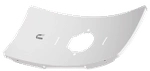 |
| 2 x Pairs of side reflector panels |
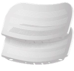 |
| 2 x Feed receiver |
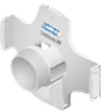 |
| 2 x Ball joint mount |
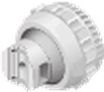 |
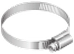
| 2 x Metal strap for tube mounting |
 |
| 4 x Set screws |
 |
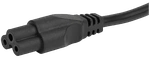
| 2 x IEC AC C5 type power cord |
 |
| Send Aareff STL Digital Encoder sticker fitted RED |
 |
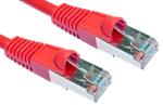
| Send 30mt cat6 stp/ftp screened network cable marked RED |
 |
| Send antenna feed with 10.41.48.20 sticker fitted RED |
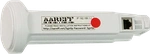 |
| Receive Aareff STL Digital Decoder sticker fitted BLUE |
|
| Receive antenna feed with 10.41.48.30 sticker fitted BLUE |
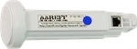 |
| Receive 30mt cat6 stp/ftp screened network cable marked BLUE |
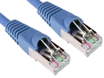 |

SHORT RANGE USE (LESS THAN A FEW HUNDERED METERS)
If you only intend to use this STL at short range, less than a few hundred meters you don't need to assemble the whole parabolic reflector antenna. You can simply use the antenna feed alone. Just point the encoder and decoder antenna feeds toward each other.
The simplest arrangement can be as shown above. Or you can extend the antenna feeds to a high or different location with the 30mt red and blue CAT6 cables.
If you intend to use the STL this way in short range, skip the next two sections LONG RANGE USE (UP TO 15kM) ASSEMBLE THE PARABOLIC ANTENNA REFLECTORS and INSTALL THE PARABOLIC ANTENNAS and go straight to the section INSTALL THE AAREFF STL DIGITAL ENCODER
LONG RANGE USE (UP TO 15kM) ASSEMBLE THE PARABOLIC ANTENNA REFLECTORS
1. Assemble the two antenna reflectors by attaching the Side Reflector Panels to the Center Reflector Panel:
a. Insert the heads of the two mounting studs on the Center Reflector Panel into the large opening of the slotted holes of a Side Reflector Panel.
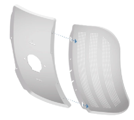
b. Slide the Side Reflector Panel down until the top edges of the panels align. The Side Reflector Panel is captured when both heads of the mounting studs are positioned over the narrow opening of the slotted holes.
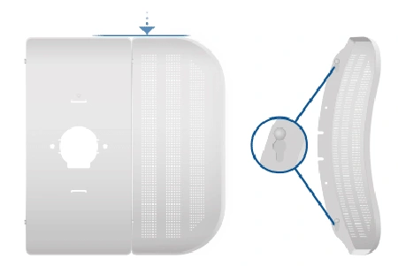
c. Repeat the assembly for the receive Side Reflector Panel.
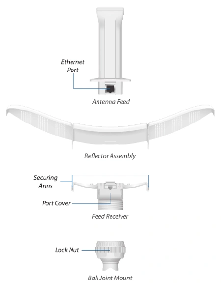
2. Hold the reflector assembly by hand (do not use a table top or flat surface) and insert the Feed Receiver into the reflector assembly to secure the panels:
a. Align the arrows on the Center Reflector Panel and the Feed Receiver, and insert both edges of the Side Reflector Panels and Center Reflector Panels into the securing arms of the Feed Receiver.
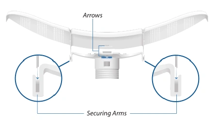
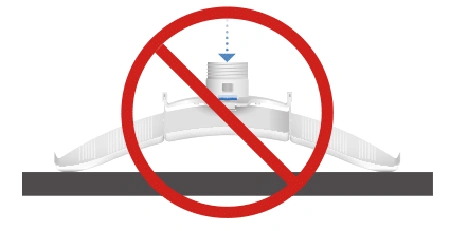
 WARNING!
Do not install the Feed Receiver into the reflector assembly by pushing down onto a table top or other flat surface as this can deform the panels. Hold the reflector assembly by hand.
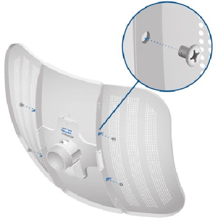
b. Insert the Feed Receiver into the Center Reflector Panel by pressing the top and bottom snap hooks into the slots of the Center Reflector Panel.
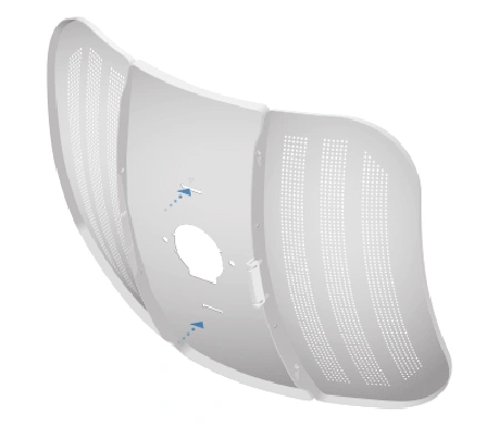
(Optional) For additional support, attach four M3x4 self tapping screws (not included) to the antenna assembly.
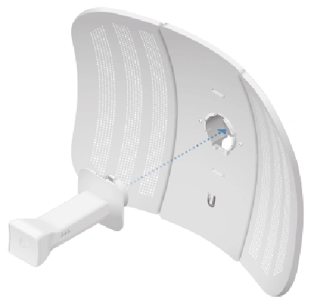
3. Insert the Antenna Feeds marked in RED and in BLUE into the Feed Receiver until the feed locks into place.
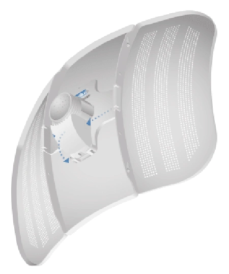
4. Press both sides of the Port Cover and detach it from the Feed Receiver.
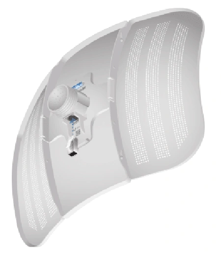
5. Connect the 30 METRE CAT5/6 STP/FTP SCREENED NETWORK CABLE marked in RED to the RJ45 connector of the SEND ACTIVE ANTENNA (10.41.48.20) also marked in RED.
6. Connect the 30 METRE CAT5/6 STP/FTP SCREENED NETWORK CABLE marked in BLUE to the RJ45 connector of the RECIEVE ACTIVE ANTENNA (10.41.48.30) also marked in BLUE.
Make sure both are pushed and locked into the holes properly, these are heavy CAT6 cables and sometimes a little extra push is needed to get them to click into place.
INSTALL THE PARABOLIC ANTENNAS
1. Attach the Ball Joint Mount to the Feed Receiver by turning the Lock Nut clockwise by hand. Do not tighten the nut.
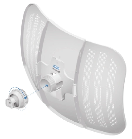
2. Open the Metal Strap and feed it through the base of the Ball Joint Mount.
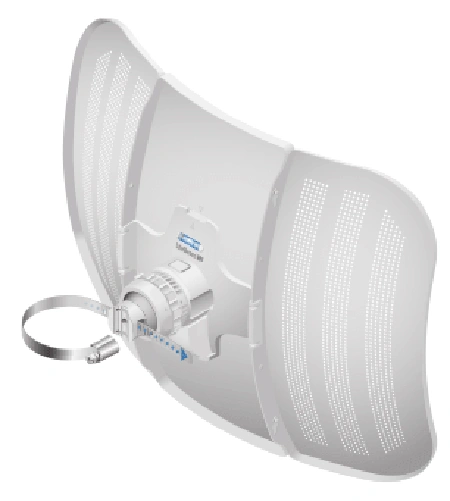
3. Wrap the Metal Strap around the pole. Use a 7 mm socket wrench or screwdriver to turn the screw clockwise and securely fasten the strap to the pole.
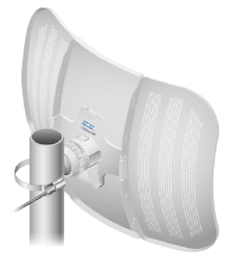
4. Remove the Port Cover and then loosen the Lock Nut on the Ball Joint Mount.
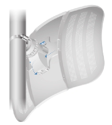
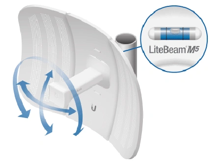
5. Aim the Antenna Feed towards each other forming the STL radio path. Use the bubble level to ensure level alignment, and then lock the aim by hand tightening the Lock Nut.
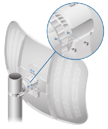
6. Locate the two holes on the Lock Nut, and fasten a Set Screw into each hole to securely lock the aim.
7. Run the 30 meter RED and BLUE cables down to the inside of the studio and transmitter where the Aareff STL Digital Encoder and Decoders are located. These cables should be strapped tight against the metal structure of the tower or pole, this will prevent potential interference problems from the main FM transmitter antennas
INSTALL THE AAREFF STL DIGITAL ENCODER
◼ RCA Unbalanced 0dBu version
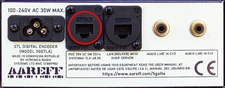
◼ XLR version
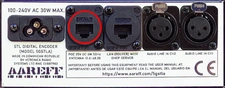
◼ Two Studio Switcher with XLR version
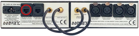
There are three versions of this unit shown in the preceding images. Make reference to the one you have.
All versions of this unit are pre-configured to stream Opus encoded digital audio to the Send Antenna Feed marked RED
1. Situate and connect the audio from the studio output directly into AUDIO LINE IN CH1/CH2 or STUDIO 1/2 CONSOLE MASTER LEFT/RIGHT
2. Connect the 30 meter cable marked in RED to the RJ45 POE 25V DC 5W 5GHz socket.
3. Connect the unit to the AC electricity supply between 100V and 240V.
WAIT 45 SECONDS FOR BOOT
and then the front panel meter should light up red. It will change to blue permanently when the link STL is fully connected with a good signal. If there is no connection to main transmitter site or the receive end of the STL it will flash blue every 5 seconds while it is trying to connect.
Okay, that is the studio and send active antenna installed and operational 👍
Now go to the main transmitter site or the receive end of the STL where ever it may be.
INSTALL THE AAREFF STL DIGITAL DECODER
◼ RCA Unbalanced 0dBu version
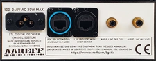
◼ XLR version
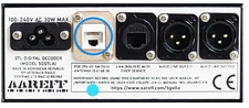
There are two versions of this unit shown in the images. Make reference to the one you have.
This unit is pre-configured to decode the opus encoded audio stream coming down the 30mt cable from the Receive Antenna Feed marked BLUE
1. Connect the audio LINE OUT from this unit directly into the input of the Aareff Limiter ALSCB or other transmitter input.
2. Connect the 30 metre cable marked in BLUE to the RJ45 POE 25V DC 5W 5GHz socket.
3. Connect the unit to the AC electricity supply between 100V and 240V.
WAIT 45 SECONDS FOR BOOT
and then the front panel meter should light up red. It will change to blue permanently when the link STL is fully connected with a good signal. If there is no connection between the STL send and receive points or the signal is bad, it will stay red. If the connection between Aareff STL Decoder and the Receive Antenna Feed (the 30mt cable) is faulty or not connected, it will flash blue every 5 seconds and while it is trying to connect.
FINAL CHECK
If the both active antennas SEND and RECEIVE are pointing at each other with no buildings or trees blocking the view between them, then the STL should activate and start working.
It is normal to take
UP TO 120 SECONDS
for the whole system to boot up and start transferring audio
LAN AND INTERNET MONITORING
Connect the back of the Encoder or Decoder or both to any available LAN port on the back of your internet router. You can use a standard network cable with RJ45 plugs fitted of any length to do this. If you have an internet connection the Encoder and Decoder will automatically connect via the router to our website to show the status of the STL.
The url for this is:
https://www.aareff.com/ipconnect/[serial number]
So, for example if your serial number of your equipment is 'decoder-600340' then the url will be:
https://www.aareff.com/ipconnect/encoder-600340/
ACTIVE ANTENNA SPECIFICATIONS
| Dimensions | 347 x 260 x 208 mm |
| Weight | 0.7 kg |
| Operating Frequency | Worldwide 5150 - 5875 MHz
USA 5150 - 5250, 5725 - 5850 MHz |
| Networking Interface | 10/100 Ethernet Port |
| Antenna Gain | 23 dBi |
| Max. Power Output | 25 dBm |
| Max. Power Consumption | 4W |
| Power Supply | 24V DC POE from Aareff encoder/ decoder units |
| Wind Survivability | 200 km/h (125 mph) |
| Wind Loading | 176.86 N @ 200 km/h |
| ESD/EMP Protection | ±24kV Contact / Air |
| Shock and Vibration | ETSI 300-019-1.4 |
| Operating Temperature | -40 to 70° C |
| Operating Humidity | 5 to 95% Non-condensing |
| Certifications | CE, FCC, IC |
DIGITAL ENCODER AND DECODER SPECIFICATIONS
| Dimensions | 483 x 150 x 89 mm (19 inch rack 2U) |
| Weight | 2.3 kg |
| Networking Interface RF | 10/100 Ethernet Port POE 24V DC |
| Networking Interface DHCP | 10/100 Ethernet Port |
| Audio Input/Output | Stereo Optional: XLR Balanced or RCA Unbalanced |
| Audio Codec | Opus 96 kb/s Stereo 48000Hz 16 bit |
| Transport Protocol | UPD/RTP Low Latency (less than 0.5 sec) |
| Max. Power Consumption | 30W |
| AC Mains Voltage | 100V to 260V 50-60Hz |
| ESD/EMP Protection | ±24kV Contact / Air |
| Shock and Vibration | ETSI 300-019-1.4 |
| Operating Temperature | -20 to +40° C |
| Operating Humidity | 5 to 95% Non-condensing |
LEGAL ADVICE
We sell this equipment to professionals and organizations in good faith it will be used correctly and legally. Nearly every country in the world require licensing for this type of equipment. It is the customer's responsibility to check relevant laws, directives, regulations and licensing requirements before installing or putting this product into service with an antenna system. You, the customer or user agree to defend, indemnify and hold harmless Aareff Systems Limited, it's employees and agents, from and against any claims, actions or demands, including without limitation legal and accounting fees, alleging or resulting from improper or unlawful use of this equipment.
© 2026 AAREFF SYSTEMS LIMITED
ALL RIGHTS RESERVED. Aareff is a trademark of Aareff Transmission Systems. All contents of this document including, but not limited to the images, logos, text, illustrations are protected by copyrights, trademarks and other intellectual property rights which are owned and controlled by Aareff Transmission Systems or by other parties that have licensed their material to Aareff Transmission Systems. This document in part or whole may not be copied, reproduced, republished, uploaded, posted or distributed in any way, including by e-mail, ftp or any other electronic means
Every care has been taken in the preparation of this document, errors in content, typographical or otherwise, may have occurred. If you have comments concerning its accuracy, please contact Aareff Systems Limited (UK)