+1 829 698 0733
What Do You Need? Talk To Us
+1 829 698 0733
What Do You Need? Talk To Us
8am-4pm EST/NY Monday-Friday
info@aareff.com 
Veronica® 1W FM Exciter (V14) | DDS PLL Broadcast

|
5 YEARS
LIMITED WARRANTY
|
- DDS REFERENCED PLL
- LOW NOISE BETTER THAN -80dBu
- FLAT 20Hz-76KHz MPX INPUT FOR AGGRESSIVE AUDIO PROCESSORS
- EXCEEDS CE/FCC TECHNICAL SPECIFICATION
- HIGH VSWR PROTECTED
- BUILT-IN 50 OHM DUMMY LOAD
- DYNAMIC RDS OPTION
Hybrid DDS & PLL: Why It’s the Gold Standard
Most competitors use "Pure DDS," which creates high-frequency noise (spurs) that can degrade your audio and interfere with other stations. The Veronica® exciter solves this with a hybrid design: the precision of digital combined with the spectral purity of high-end analog.
-
Pure Signal Foundation: We run the DDS at low frequencies where it is mathematically perfect, guaranteeing a clean base signal far away from the "noise limits" of digital tech.
-
Analog Purity Upconversion: That pristine signal is multiplied into the FM band using an ultra-low-noise PLL. This eliminates the "digital jitter" found in cheaper exciters.
-
Unmatched -80dBu Noise Floor: You get absolute frequency agility with the legendary "analog warmth" and spectral purity required for professional, legal broadcasting.
Ultra-Low Noise Modulator
Our Hartley loosely coupled Push-Pull Voltage Controlled Oscillator (VCO) delivers industry-leading stability, remaining within 10kHz of its target frequency even when the DSS and PLL are disabled. This inherent precision means the PLL requires only minimal correction to maintain an accuracy of less than 300Hz.
This advanced architecture provides two critical advantages:
1. Ultra-Low Phase Noise: Superior audio transparency as a result of reduced PLL intervention.
2. Precision Low-End Response: By utilizing a super-low frequency loop filter, the system does not mistake 30Hz bass signals for frequency drift. This allows deep low-frequency audio to pass to the varicap completely unaffected—a requirement for broadcasters using high-performance audio processors.
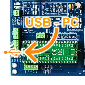
Intuitive USB PC Control & Telemetry
Take full command with our custom-engineered PC control software. Interfacing directly with the PLL DDS microprocessor via USB, this lightweight app provides real-time telemetry and configuration on your desktop.
- Plug-and-Play: Native Windows 10/11 compatibility with no third-party drivers required. Auto-detects the exciter for an instant, secure connection.
- Real-Time Monitoring: Instantly view frequency lock status. Adjust frequency, RF output power, and internal parameters directly from the UI.
- RDS Management: Full control of the optional RDS board. Program PI codes, PTY, and live scrolling Radio Text from a single unified dashboard.
Optional Dynamic RDS Integration
Enhance your station's digital presence with our programmable RDS sub-board. This compact module plugs directly into the main exciter's SIL socket, instantly enabling advanced digital data broadcasting.
- Comprehensive Data Control: Fully customize your station's PI, PTY, static PS (Program Service) name, and scrolling Radio Text.
- Live Metadata Automation: Maintain a USB connection to your studio PC to broadcast real-time song titles, artist names, and presenter info directly to listener dashboard receivers.
- Pristine MPX Mixing: The onboard 57kHz subcarrier overlays perfectly onto your incoming multiplex (MPX) signal from an external processor or STL, ensuring flawless, low-noise integration.
Onboard 50-Ohm Dummy Load: Safe Bench Testing
We’ve integrated a premium 50-ohm load directly onto the PCB. This allows you to power up and test the exciter safely on your workbench without an external antenna.
Safe Power-Up
99% Heat Dissipation
3m Test Radius
| Varicap Component |
Dedicated Function |
| Broadband Tuning |
Delivers absolute stability across the core 84 to 112 MHz frequency span. |
| PLL Correction |
Manages exact phase-locked loop correction, completely isolating the control loop from the audio path. |
| FM Modulation |
Optimized specifically for FM, achieving better than 60dB/0.1% IMD across the 30Hz to 76kHz baseband. |
High VSWR Protected
The RF output transistor in the 1 W unit is an SD1127 rated at 4 watts, in this unit it only runs at 1 watt. Given that it is four times overrated in power it can handle 100% reflection at any phase angle without burning out and still be within it's safe working limits. Basically the output stage will not break which is a requirement for CE marking.
Flat 30Hz to 76KHz MPX Input Version: Precision for High-End Audio Processors
Professional-Grade Raw MPX Input
This version is specifically available for experienced users who require a straight, raw MPX input for external signal processing.
1. Zero Tilt for Multiband Processors
• The absolute requirement for professional processing is a flat low-frequency response. As proven by our 160Hz Square Wave Test, our input delivers a perfectly square wave with zero tilting. This allows your external processor to maintain absolute control over the modulation, ensuring maximum loudness and a legal signal without low-end artifacts.
-500.webp)
2. Ultra-Stable Hartley VCO & Slow-PLL Architecture
Superior performance starts with a stable foundation. Our Hartley-based, lightly coupled push-pull VCO is so stable it stays within 10kHz of its frequency even with the PLL turned off. This inherent stability leads to two critical performance benefits:
• Ultra-Low Noise: Because the VCO is naturally stable, the PLL only needs to make microscopic corrections (less than 300Hz), resulting in an exceptionally clean and transparent noise floor.
• Preserved Low-End: By heavily low-pass filtering the PLL control voltage to just a few Hz, we ensure 30Hz bass notes pass through the varicap completely unaltered. This preserves the essential low-frequency response demanded by high-performance audio processors.
Result: This preserves the essential low-end audio response demanded by high-performance audio processors.
Do You Have A Question?
USER MANUAL
Previous Versions:
PLL10
PLL11
PLL12
INTENDED USE / LEGAL ADVICE
This product is not intended for use on a 'stand alone' basis, it is
sold as spare part/module sub assembly and is intended as a component for use in a fully assembled transmitter and/or transmission system that as a whole complies with the engineering requirements of ETS 300 384 and ETS 300 447. Use of this product on a 'stand alone' basis will in most countries of the world contravene the EMC compatibility regulations. It is the customer's
responsibility to check relevant laws, directives and regulations before putting this product into service with an antenna system. You, the customer agree to defend, indemnify and hold harmless Aareff Systems Limited, it's employees and agents, from and against any claims, actions or demands, including without limitation legal and accounting fees, alleging or resulting from improper or unlawful use of this product.
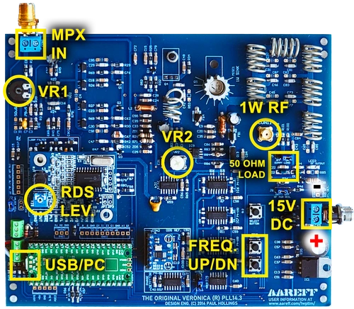
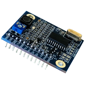
PCB ASSEMBLED
MPX IN - 10K ohm 775mV Nom. 30Hz-76KHz
VR1 - MPX Deviation. 10K ohm 775mV Nom.
VR2 - RF Power Lev. 10mW to 1000mW.
RDS LEV. - RDS Deviation. 0 to 5KHz
USB/PC - USB cable connection to PC
FREQ UP/DN - Freq. Adj. in steps of 100KHz
15V DC - 15V DC power input 600mA max.
1W RF - 50 OHM RF Output
50 OHM LOAD - Dummy Load Jumper
CIRCUIT TESTING
1. Plug in a 50 ohm dummy load to the RF output OR Reduce the power to zero by turning VR2 fully clockwise.
DO NOT EXCEED 16V DC
DO NOT CONNECT + and - THE WRONG WAY
2. Apply between 12 and 16 volts to the PCB position marked CON6 +15V (+) and 0V (-)
3. Press the UP and DOWN buttons to select the frequency you require.
6. Apply audio at line level to CON1. Adjust the VR1 for correct FM deviation.
7. Remove the 50 ohm dummy load from the output OR Increase the power to full by turning VR2 fully. You are now ready to install the 1W PLL into your transmission system.
If the 1 watt PLL is connected to a Veronica / Aareff Limiter Compressor or a Stereo Coder, pre-emphasis is not required. To disable the pre-emphasis, do not select 50uS or 75uS and remove the jumper completely. Store the jumper in a safe place just in case you need to restore the pre-emph for another application at a later date.
USB PC/RDS CONTROL
Download our free PC app that connects 'plug and play' to the transmitter / PLL DDS exciter via USB. You can see the PLL status and change the frequency and power directly from the PC interface. If you choose to add the optional RDS card, you can also change the PI, PTY and scrolling text of the radio from the interface.
Below are the download links for Windows:
https://www.aareff.com/1wpllm/pll14.4/pll14.exe
https://www.aareff.com/1wpllm/pll14.4/pll14.zip
By clicking on these links, Windows may show you a warning that the software is from an unknown publisher. We assure you that we wrote the apps and the files are perfectly safe, virus-free and come from our registered domain www.aareff.com, which you can verify at https://lookup.icann.org/en/lookup
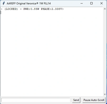
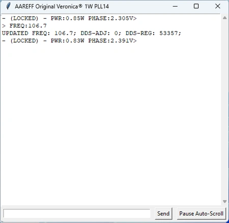
Normal state when the device is connected: the PLL is LOCKED with an output power of 0.85W and a PLL phase of 2.33V
![Original Veronica® 1W DDS PLL FM Exciter USB PC Control - Device Status]()
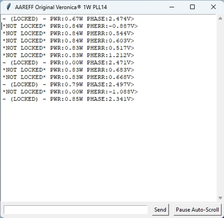
This shows what happens if the device loses its lock. We simulated a failure by placing our fingers on the oscillator coils.
![Original Veronica® 1W DDS PLL FM Exciter USB PC Control - NOT LOCKED]()
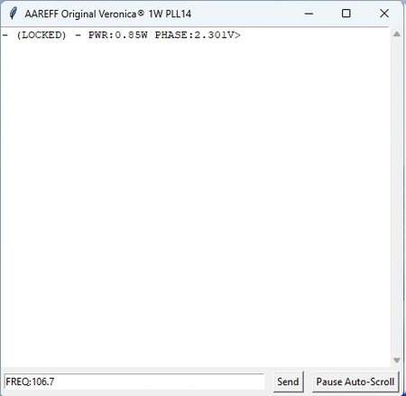
This shows the return to normal with the user command FREQ:106.7 typed in the input box below. A value between 87.5 and 108.0 MHz can be set.
![Original Veronica® 1W DDS PLL FM Exciter USB PC Control - Changing Frequency]()
After pressing 'Send:' the display returns UPDATED FREQ 106.7 along with other technical information. This causes the transmitter to change frequency.
![Original Veronica® 1W DDS PLL FM Exciter USB PC Control - Frequency Change Confirmed]()
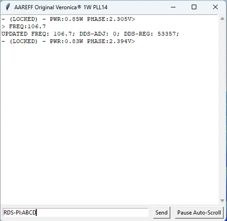
This shows another command, RDS-PI:ABCD typed for devices with the RDS card.
![Original Veronica® 1W DDS PLL FM Exciter USB PC Control - Changing RDS PI]()
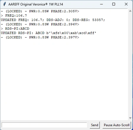
After pressing 'Send': the display returns UPDATED RDS-PI:ABCD instantly updating the RDS PI code.
![Original Veronica® 1W DDS PLL FM Exciter USB PC Control - RDS PI Change Confirmed]()
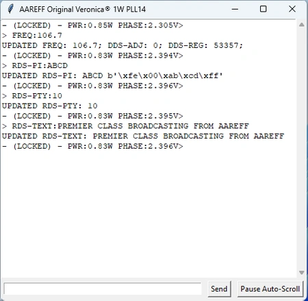
This shows two additional examples of RDS commands:
RDS-TEXT:[write your message here]
RDS-PTY:[number from 0 to 31]
Text is plain ASCII up to 60 chars and valid PTY Codes shown below.
![Original Veronica® 1W DDS PLL FM Exciter USB PC Control - RDS Text and PTY Example]()
Shown below are the current commands available for USB PC Control and also the PTY codes for program type. We will be making further developments, improvements and more useful commands to this app in the near future. Keep checking this page for details.
◼ DEVICE-ID
◼ STATUS
◼ FREQ:[87.5 to 108.0]
◼ DDS-ADJ:[-1,0 or 1]
◼ PWR:[0 to 1]
◼ RDS-PTY: [0 to 31 list of PTY codes]
◼ RDS-PI: [0000 to FFFF]
◼ RDS-TEXT:[any string up to 60 chars.]
◼ RDS-ON
◼ RDS-OFF
Additional commands following Oct 2025 firmware update
◼ RDS-PS:[any string up to 8 chars.]
◼ RDS-MS:[0 or 1]
◼ RDS-TP:[0 or 1]
◼ RDS-TA:[0 or 1]
◼ RDS-AFNUM:[0 to 15]
◼ RDS-AF:[Up to 15 freq. formatted eg. 88.1, 88.7, 94.8]
◼ RDS-DI:[0 to 31 integer]
◼ RDS-RT:[any string up to 60 chars.]
◼ RDS-SCROLL:[0 or 1]
SPECIFICATIONS
The following tests were taken at 15V DC and the worst case measurement was recorded
over the range -20 to +50 deg C.
|
Frequency | 87.5 - 108 MHz |
|
RF Output | 1W to 1.4W into 50 Ohm |
|
Deviation Sensitivity Stability | +/-2% max |
|
Spurious Emissions | 75dB rtc |
|
Harmonic Emissions | 63dB rtc |
|
Out of Lock RF Muting | 63dB rtc |
|
Freq Stability | +/- 1 KHz max typ. +/-300Hz |
|
RF Output Connector | Female N type |
|
Audio Input Sensitivity | 0dBu for +/- 75 KHz |
|
Signal To Noise Ratio | 80 dBu |
|
Audio Response | Flat from 30Hz-76KHz |
|
Pre-emphasis | (50uS/ 75uS/ None) |
|
Audio Distortion | Better than 0.1% / 60dB THD |
|
Audio Input | Unbalanced Terminal Block |
|
Power Supply | 12-15V DC 650mA max
|

DECLARATION OF CONFORMITY
AAREFF TRANSMISSION SYSTEMS SL
AVDA ANDALUCIA 1
LA ALFOQUIA-ZURGENA
04661
ALMERIA
ESPANA.
Paul Hollings
In Zurgena, Almería, Spain on 01 of November 2011, the equipment:
Original and Genuine Veronica 1W PLL (1WPLLM) meets the essential requirements of the R&TTE directive
ETS 300 384/A1 ed.1 (1997-2002) Broadcasting Systems Transmitters FM sound broadcasting in very high frequency (VHF)
It should be noted that this cannot be legally used as a standalone unit. This sub assembly is designed and intended to be installed in a fully screened EMC enclosure with or without other sub assemblies. Any final design should be further tested to verify it meets the essential requirements of:
EN 301 489-11 V1.3.1 (2006-05) Electromagnetic compatibility and Radio Spectrum Matters (EMC) for radio equipment and services. Part 11: Specific conditions for transmitting the terrestrial sound broadcasting service.
2006/95/EC DIRECTIVE 2006/95/EC of 12 December 2006 on electrical equipment designed for use within certain voltage limits.
ROHS
All components used in this apparatus are RoHS compliant and do not contain above the specified limits in any of the following restricted substances:
- Lead
- Hexavalent Chromium
- Mercury
- Cadmium
- Polybrominated Biphenyls (PBB's)
- Polybrominated Diphenylethers (PBDE's)
PRODUCT END OF LIFE
This apparatus must NOT be disposed of with other domestic waste.
We are fully committed to maintaining our responsibilities to the environment. Owners of apparatus that has reached the end of it's useful life can return it to us for recycling, recondition, reuse or proper disposal. You will be required to pay lowest cost postal service available to ship the apparatus to us. Before shipping please contact us for more important information.
© 2026 AAREFF SYSTEMS LIMITED
ALL RIGHTS RESERVED. Aareff is a trademark of Aareff Transmission Systems. All contents of this document including, but not limited to the images, logos, text, illustrations are protected by copyrights, trademarks and other intellectual property rights which are owned and controlled by Aareff Transmission Systems or by other parties that have licensed their material to Aareff Transmission Systems. This document in part or whole may not be copied, reproduced, republished, uploaded, posted or distributed in any way, including by e-mail, ftp or any other electronic means
Every care has been taken in the preparation of this document, errors in content, typographical or otherwise, may have occurred. If you have comments concerning its accuracy, please contact Aareff Systems Limited (UK)