 +1 829 698 0733
What Do You Need? Talk To Us
+1 829 698 0733
What Do You Need? Talk To Us8am-4pm EST/NY Monday-Friday info@aareff.com

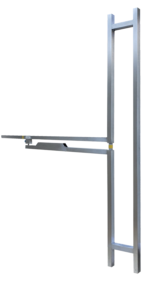
High Power 3kW Broadband FM Dipole Antenna
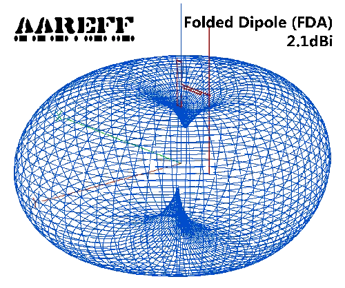
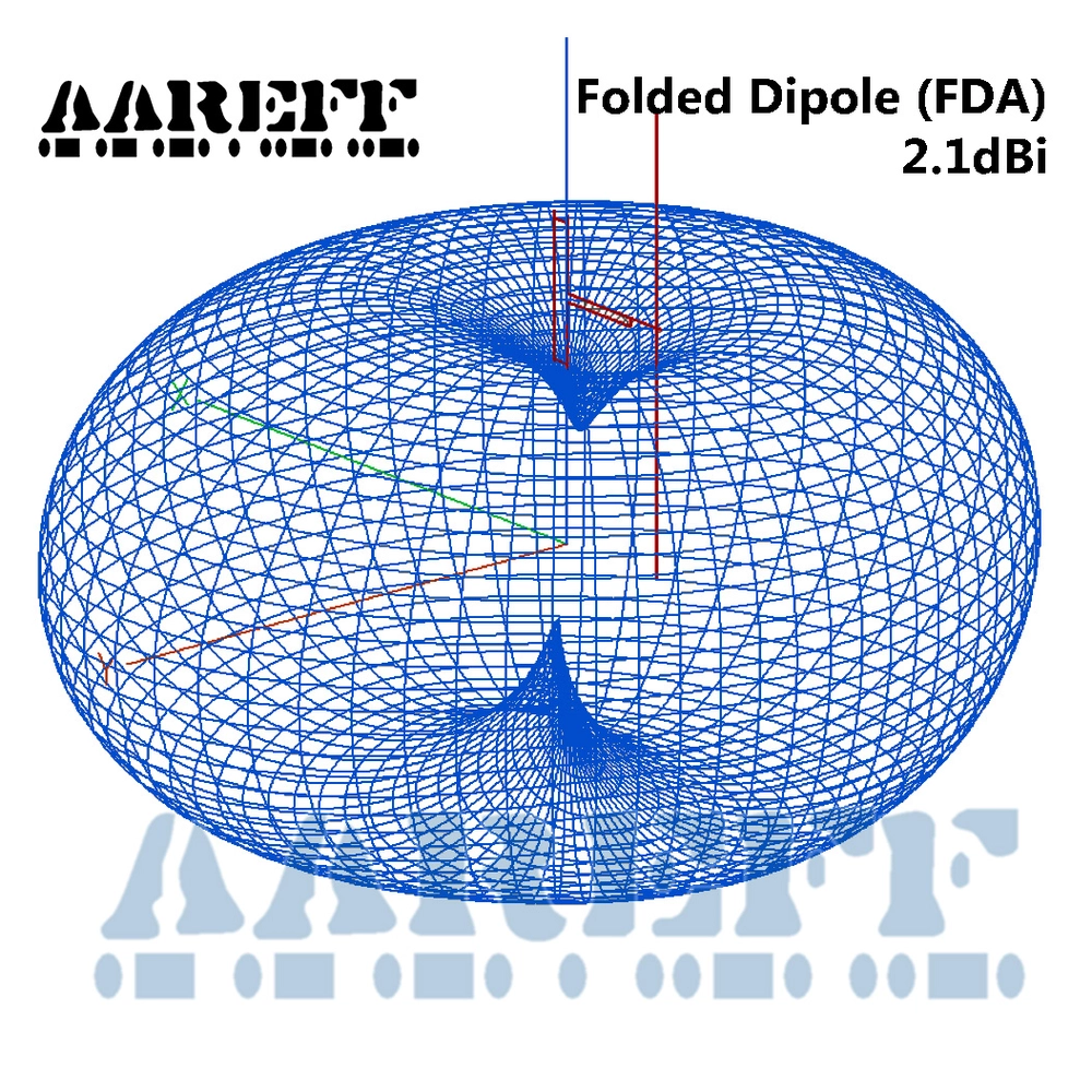
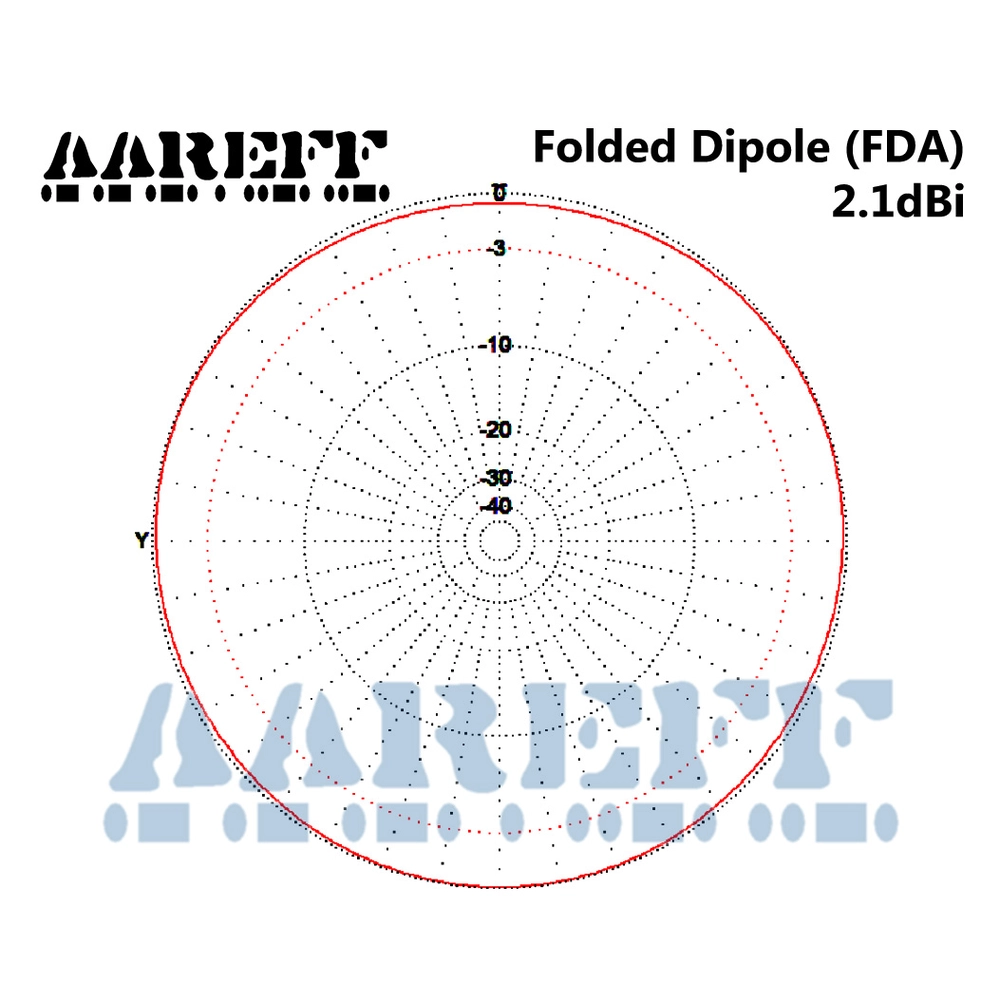
- 2.2dBi Gain (x1.6 TRANSMITTER POWER)
- SUPER 3kW HIGH POWER CAPABILITY
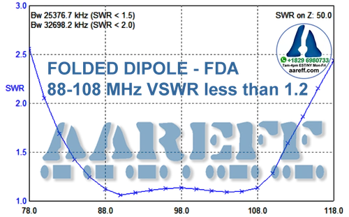
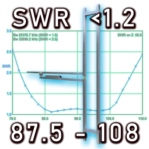
- VSWR ≤ 1.2 FROM 87.5 TO 108 MHz
- BROADBAND 87.5 TO 108 MHz
- NO TUNING, FULL BAND OPERATION
- AVAILABLE WITH DIN 7-16 CONNECTOR
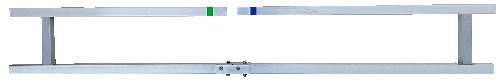
- LIGHTWEIGHT AT UNDER 3Kg
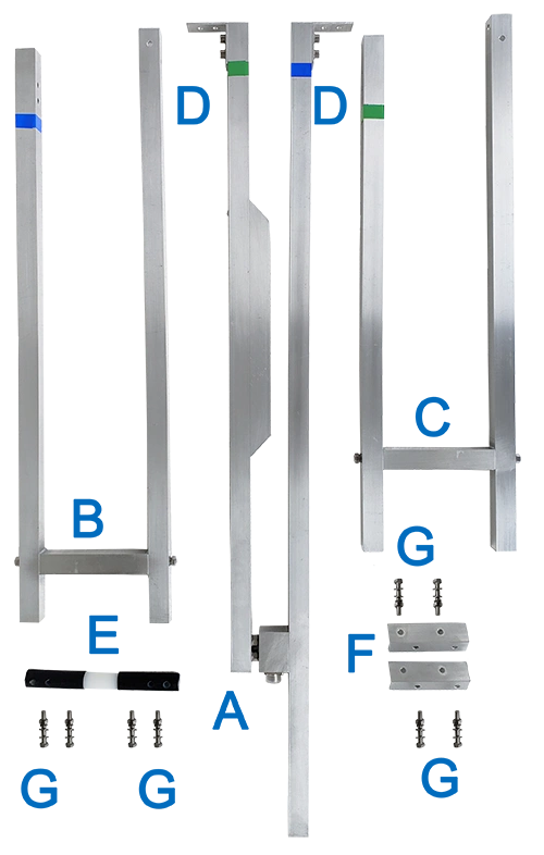
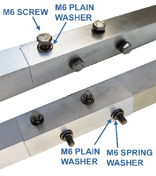
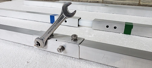
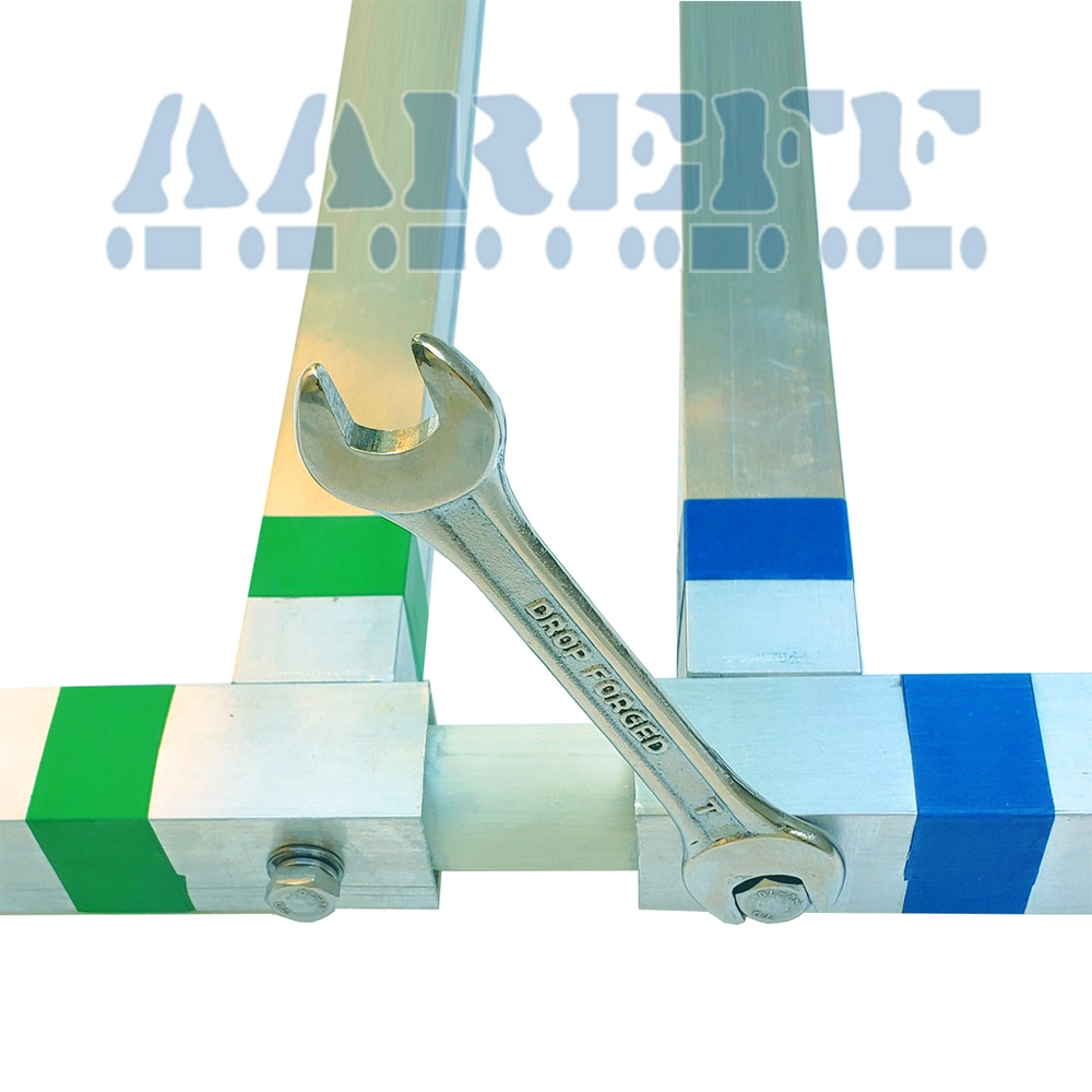
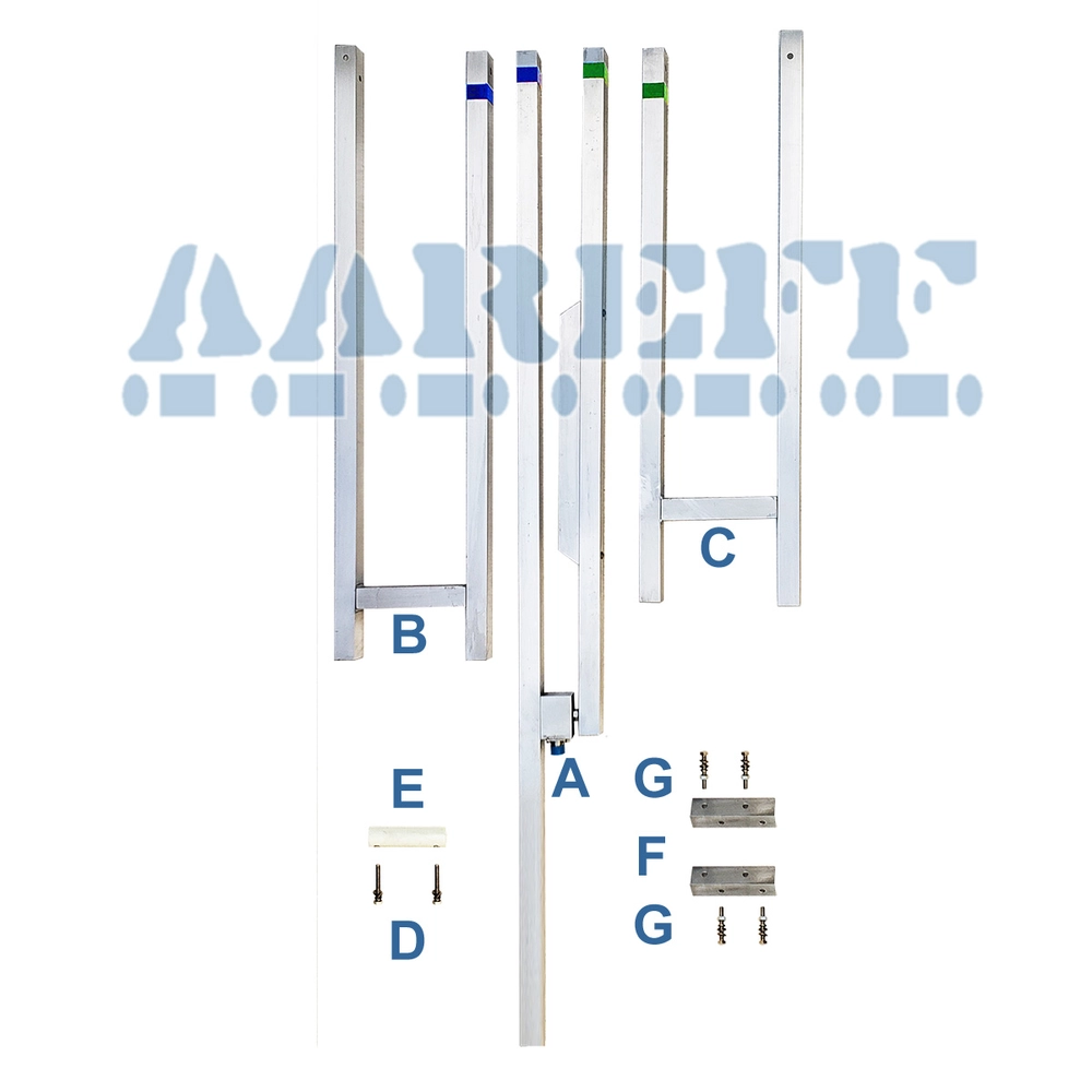
- EASY ASSEMBLING FOR NOVICES
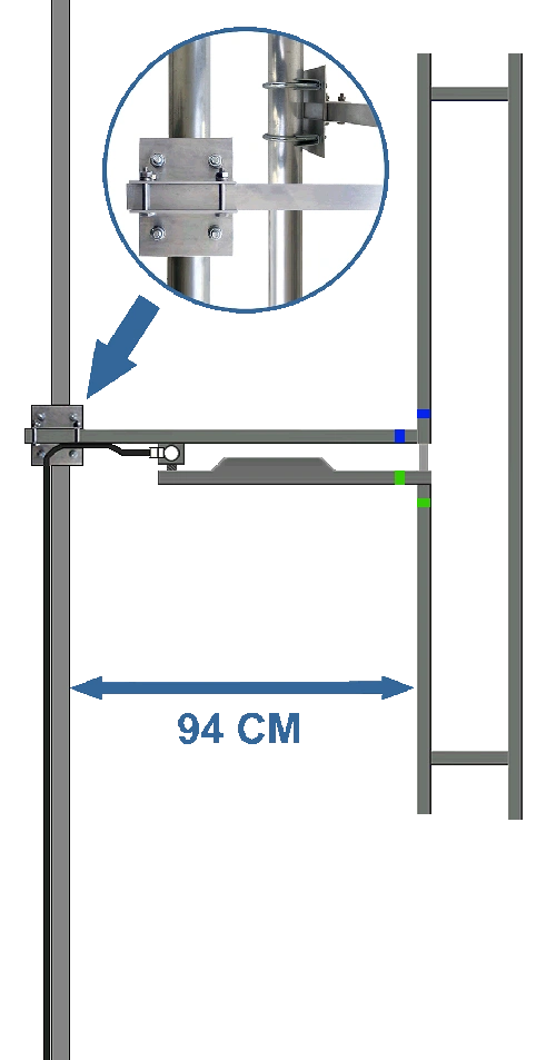
- EASY INSTALLATION
- PRICE INCLUDES SHIPPING
YouTube
Scalable Architecture: Stacking for High Gain
Our folded dipoles are engineered for seamless array integration using professional power splitters and phasing harnesses. By stacking in configurations of 2 to 8 bays, you can achieve substantial gain increases—reaching over 11dBi for long-range broadcast applications.
This high-gain efficiency delivers massive Effective Radiated Power (ERP) with minimal transmitter overhead. For example, an 8-bay array can transform just 8kW of output into a powerful 100kW EIRP, reducing electrical consumption while maximizing your station's signal footprint.
High-Power Engineering: 3kW Sustained Capacity
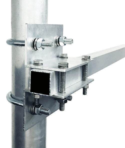
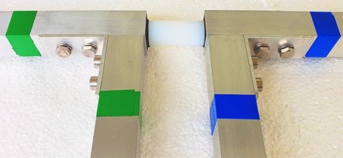
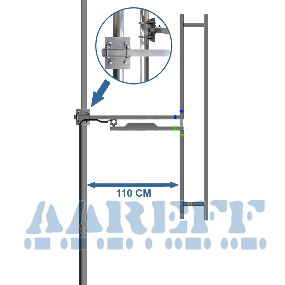
Our design eliminates failure-prone coils and capacitors by using precision parallel matching tubes for 50-to-300 ohm impedance transformation. This integrated balun architecture ensures virtually zero residual current on the coaxial outer conductor, providing exceptional common-mode rejection and system stability.
Built from robust 25mm square tubing with high-dielectric PTFE (Teflon) insulators, the antenna features an optimized RF path with zero thermal accumulation. While it easily sustains 3kW of continuous power, this limit is defined only by the industry-standard 7-16 DIN connector, leaving the internal radiator far below its physical threshold.
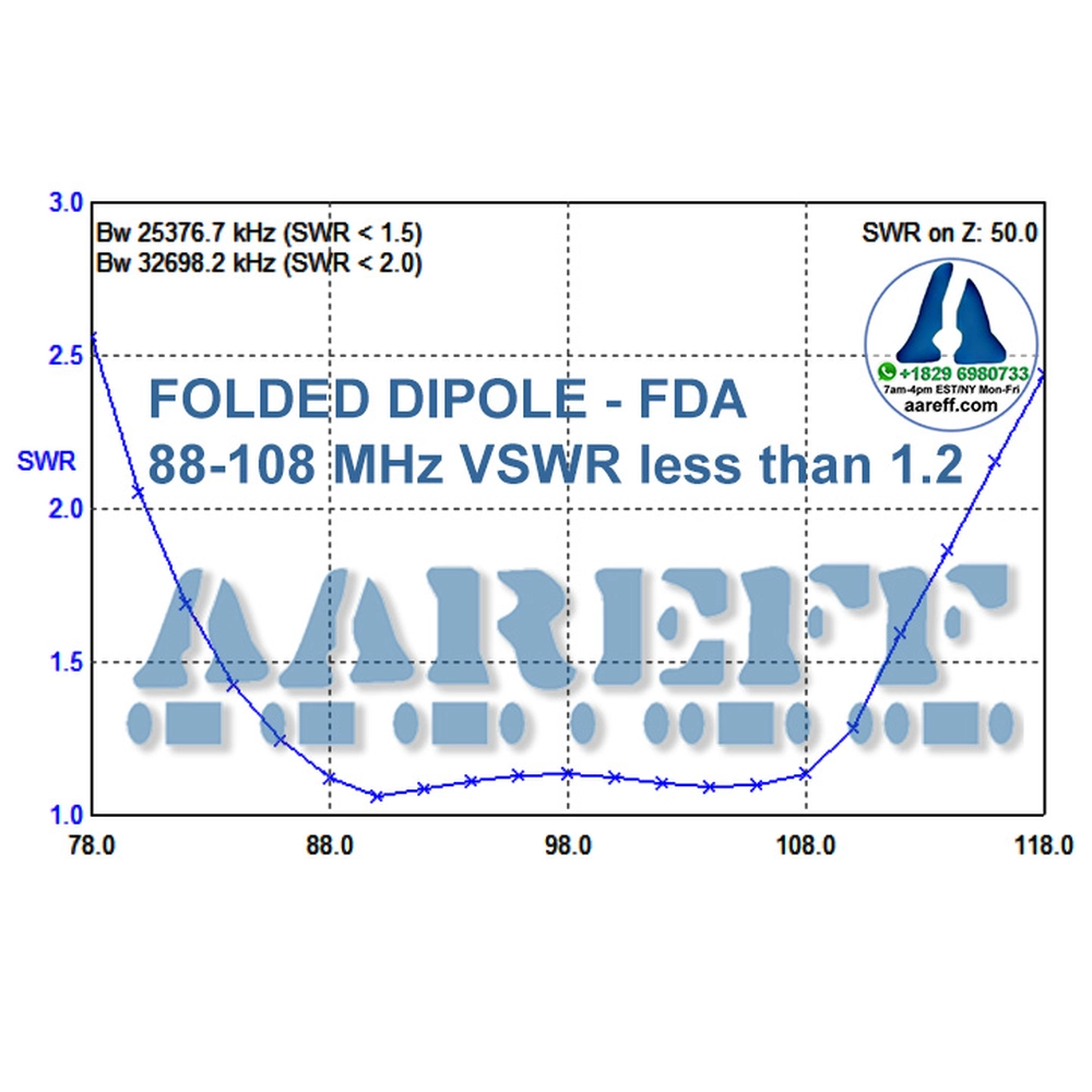
Advanced Broadband Performance: 25MHz with VSWR < 1.5
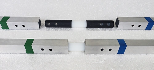
Through extensive R&D and electromagnetic modeling, we have re-engineered the classic folded dipole using a proprietary H-section terminal configuration. This optimized design significantly expands the operational range while maintaining exceptional impedance matching.
The result is a near-perfect VSWR of 1.0 to 1.1 across the entire 25MHz band. This broadband stability ensures maximum power transfer and eliminates the need for re-tuning, providing a professional,
Optimized for 100kW EIRP High-Power Systems
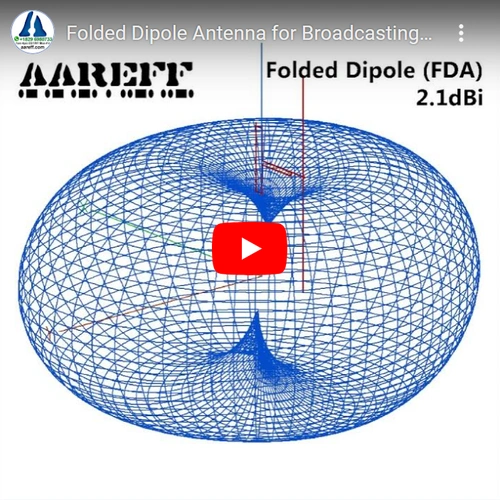
Our Folded Dipole was originally engineered as the high-performance cornerstone for the Aareff 100000W EIRP Transmitter System. You can see this architecture in action and understand the technical advantages in our comprehensive system overview on YouTube.
To meet the rigorous demands of 100kW installations, this antenna was developed with three critical engineering mandates:
1. Sustained High-Power Capacity: Effortless handling of multi-kilowatt inputs.
2. Precision Stackability: Modular design for high-gain array configurations.
3. Ultra-Broadband Performance: A plug-and-play VSWR profile that ensures a successful installation even in challenging tower environments.
By eliminating the need for complex field-tuning, we have simplified the deployment process for tower crews, ensuring peak performance regardless of installation height or location.
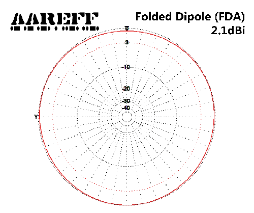
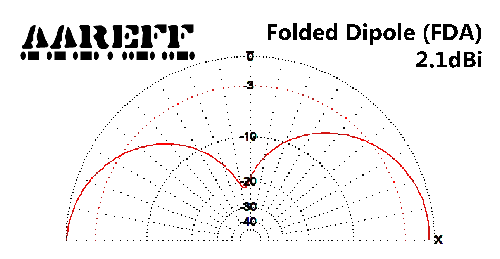
| Gain (Isotropic) | +2.1 dBi |
| Frequency Range | 87 - 109 MHz |
| Bandwidth | +/-12 MHz 1.5 VSWR |
| Construction | Glass Fibre/Aluminum |
| RF Connectors | N type / DIN 7-16 |
| Impedance | 50 ohm unbalanced |
| Polarization | Vertical |
| Maximum RF Power | 0.8kW / 1.6kW / 3kW |
| Weight of Antenna | 2.3Kg |
| Wind Speed Handling | 90 MPH |
Do you want cable for your antenna?


 IMPORTANT!