FAQ FREQUENTLY ASKED QUESTIONS
Choosing FM Broadcast Equipment: The Comprehensive Radio Station Starter List.
Build your radio station with AAREFF
Before delving into the specific technical specifications and detailed selection process, this guide provides a clear, scannable overview of the core FM broadcast equipment required to successfully launch and operate your new station. We simplify the setup process so you can get on air faster and within budget.
Essential Equipment Required to Launch
Your new radio station requires investment in two fundamental areas: the Transmitting System and the Studio Equipment.
Transmitting System (Broadcast Site):
- FM Broadcast Transmitter
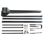
- FM Antenna (FM VHF Dipole Recommended)
- Coaxial Antenna Cable
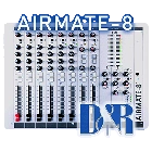
- Console Mixer
- Microphones with Stands (can begin with 2 units)
- Headphones (can begin with 2 units)
- Computer (For Automation/Playback)
- Studio Furniture
Critical Factors for Broadcast Performance.
A radio station's broadcast performance and market reach are fundamentally determined by four critical technical and regulatory factors:
1. Transmitter Power
2. Antenna System Design
4. Regulatory Compliance (EIRP)
Example: Affordable Community Broadcast Setup
For broadcasting across a small community (e.g., covering approximately 10 km), we recommend starting with a full EIRP compliant package for immediate and reliable operation.
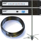
Recommended System: The 20W EIRP Complete FM Radio Transmitter Broadcasting System.
- Transmitter: 20W FM Stereo Transmitter with Integrated Audio Processing.
- Antenna System: Standard FM VHF Dipole with 12m of Coaxial Cable.
You can begin broadcasting on your own radio station with a remarkably reasonable budget and a focused equipment selection.
Get a pro forma contacting is at info@aareff.com
Do I need a license?
Yes, before you invest in any broadcast equipment or finalize your studio design, you must consult your national broadcasting authority. Checking with them ensures you secure the proper frequency and are in full compliance with all legal and regulatory requirements for radio transmission in your country.
How to Order Your FM Broadcast Equipment.
Simple, Secure Ordering Process for Custom AAREFF FM Transmitters.
Ordering your customized AAREFF FM broadcast equipment is a straightforward two-step process. We focus on speed and accuracy to get your equipment produced and dispatched efficiently. .
1. Place Your Order:
- Secure Website Order: Place your order directly using our secure server at checkout.
- Request a Pro Forma Invoice Ideal for institutional or bank transfers
2. Order Confirmation:
You will receive an email containing all confirmation and payment details for your purchase.
3. Custom Programming Request:
We immediately begin production (or pull stocked equipment) and will promptly request your intended broadcast frequency and RDS text (Radio Data System).
4. Testing & Configuration:
We require a test frequency to ensure your FM Transmitter is fully functional. We prefer to set your specific frequency and RDS text (anywhere between 87.5MHz and 108.0 MHz, so the equipment is ready to use out of the box.
5. Dispatch & Tracking:
Once final testing is complete, your equipment is professionally packed and dispatched. You will receive a final email containing your shipping tracking number for monitoring delivery.
Taxes, duties, and import fees are the recipient's responsibility and are country-specific (unless prepaid at checkout).
FM TRANSMITTER GLOBAL SALES & DISTRIBUTION: WORLDWIDE REGIONS AND COUNTRIES SERVED
We are proud to supply our complete line of reliable, low-power and high-power AAREFF FM Transmitters and broadcasting equipment to a vast global market.
Our sales, installation, and remote maintenance support cover the following continents and regions:
North & South America
- North America- Central America
- The Caribbean
- South America
Antigua and Barbuda, Argentina, The Bahamas, Barbados, Belize, Bolivia, Brazil, Chile, Colombia, Costa Rica, Cuba, Dominica, Dominican Republic, Ecuador, El Salvador, Grenada, Guatemala, Guyana, Haiti, Honduras, Jamaica, Mexico, Nicaragua, Panama, Paraguay, Peru, Saint Kitts and Nevis, Saint Lucia, Saint Vincent and the Grenadines, Suriname, Trinidad and Tobago, Uruguay, Venezuela.
Europe & CIS
- Western Europe- Eastern Europe
- European Union
Albania, Andorra, Armenia, Austria, Azerbaijan, Belarus, Belgium, Bosnia and Herzegovina, Bulgaria, Croatia, Cyprus, Czech Republic, Denmark, East Timor (Timor-Leste), Estonia, Finland, France, Georgia, Germany, Greece, Hungary, Iceland, Ireland, Italy, Kosovo, Latvia, Liechtenstein, Lithuania, Luxembourg, Malta, Moldova, Monaco, Montenegro, Netherlands, North Macedonia, Norway, Poland, Portugal, Romania, Russia, San Marino, Serbia, Slovakia, Slovenia, Spain, Sweden, Switzerland, Turkey, Ukraine, United Kingdom, Vatican City.
Africa & Middle East
- North Africa- Sub-Saharan Africa
- The Middle East
Algeria, Bahrain, Djibouti, Egypt, Iran, Iraq, Israel, Jordan, Kuwait, Lebanon, Libya, Morocco, Oman, Qatar, Saudi Arabia, Syria, Tunisia, United Arab Emirates, Yemen.
Angola, Benin, Botswana, Burkina Faso, Burundi, Cabo Verde, Cameroon, Central African Republic, Chad, Comoros, Democratic Republic of the Congo, Congo, Côte d’Ivoire, Equatorial Guinea, Eritrea, Eswatini, Ethiopia, Gabon, The Gambia, Ghana, Guinea, Guinea-Bissau, Kenya, Lesotho, Liberia, Madagascar, Malawi, Mali, Mauritania, Mauritius, Mozambique, Namibia, Niger, Nigeria, Rwanda, Sao Tome and Principe, Senegal, Seychelles, Sierra Leone, Somalia, South Africa, South Sudan, Sudan, Tanzania, Togo, Uganda, Zambia, Zimbabwe.
Asia & Oceania
- Asia- Australia
- Oceania
- The Pacific Islands
Afghanistan, Australia, Bangladesh, Bhutan, Brunei, Cambodia, Fiji, India, Indonesia, Japan, Kazakhstan, Kiribati, South Korea, Kyrgyzstan, Laos, Malaysia, Maldives, Marshall Islands, Federated States of Micronesia, Mongolia, Myanmar, Nauru, Nepal, New Zealand, Pakistan, Palau, Papua New Guinea, Philippines, Samoa, Singapore, Solomon Islands, Sri Lanka, Taiwan, Tajikistan, Thailand, Tonga, Tuvalu, Turkmenistan, Uzbekistan, Vanuatu, Vietnam.
Optimized FM Transmitter Selection Guide
Find Your Ideal Professional FM Transmitter in 3 Steps
Step 1: Define Your Coverage
Choosing the correct FM transmitter for your project—from your first low-power FM station to a multi-kilowatt regional broadcaster—is simple. Our equipment is engineered to provide professional, CE/FCC-compliant performance for every level of broadcast engineer.
- Low Power EIRP (0.1W – 30W): Ideal for community radio and neighborhood coverage (1 to 12 km). Perfect for low-power FM transmitters for schools, churches, and local projects.
- Medium Power EIRP (50W – 500W): Provides reliable city-wide FM coverage (16 to 49 km). Matches the performance of our robust 500W FM transmitters for regional use.
- High Power EIRP (1kW – 100kW): Delivers wide-area regional coverage (60 km up to 195 km). Essential for our professional 10kW and 100kW FM transmitter systems demanding maximum reach and reliability.
Step 2: Consider the Environment
Our professional FM transmitters are rigorously tested and proven reliable in the world's most demanding environments, including tropical climates, deserts, and areas with unstable power grids. The robust design ensures optimal operation when paired with proper ventilation and humidity control.
Step 3: Think Ahead
Many of our clients successfully start with low-power FM equipment and seamlessly scale their coverage later. All AAREFF transmitters are designed with future growth in mind, protecting your initial investment as your station expands.
- 5 Year Warranty: An industry-leading guarantee on your investment.
- CE/FCC Compliant: Meets all major international broadcast equipment standards.
- Ready-to-Broadcast: Equipment delivered fully tested and configured for immediate use.
- Years of Expertise: Confidence built on more than 25 years of specialized broadcasting experience.
Contact our broadcast engineering team today to discuss your project and receive a quote for the perfect FM transmitter package at info@aareff.com
FAQs for Community Broadcasters: Reliable FM Broadcasting for Small Towns & Community Stations
OPTIMIZE YOUR RADIO BROADCAST WITH THE AAREFF 10W - 30W DDS FM TRANSMITTER TODAY. ENGINEERED TO DELIVER RELIABLE FM SERVICE, EASY SETUP, AND ROBUST SUPPORT.
Is RDS programmable?
Yes, RDS can display your station name and real-time song info using PC software for dynamic text updates.
.
Who should use the 10W to 50W transmitter?
Ideal for community broadcasters, local radio stations, and municipal services requiring reliable audio transmission up to small-town distances.
Can the power output be adjusted?
Yes, via a simple control on the unit, allowing you to comply with specific license limits.The output power is continuously adjustable from:
• 1 Watt up to 10 Watts
• 1 Watt up to 20 Watts
• 1 Watt up to 30 Watts
• 1 Watt up to 50 Watts
Can I connect an antenna and cable to the 10W - 50W FM transmitter, and what is its EIRP?
Yes, you can easily connect an external antenna and cable to our FM transmitters for powerful, reliable broadcasting. This setup is ideal for achieving clear FM coverage in small towns and for community stations. For maximum range and clarity, we strongly recommend using low-loss feeder cables such as LMR400.
• 10W EIRP
• 20W EIRP
• 30W EIRP
• 50W EIRP
Can I connect a professional audio mixer?
Absolutely. The unit features an industry-standard XLR True Balanced 600 ohm input, perfectly compatible with professional studio mixers and audio equipment.
What is the power requirement?
The unit features a wide-ranging, efficient power supply that accepts 90 to 264 V AC (100V, 110V, 220V, 240V AC) at 50/60 Hz, ensuring reliable operation worldwide.
Contact & Ordering
For advice or a custom quotation, email info@aareff.com or call +1 829 698 0733. Fast delivery and expert support included.
.
Combining Multiple FM Transmitters into a Single Antenna: Solutions and Best Practices
THE CHALLENGE OF COMBINING FM TRANSMITTER OUTPUTS.
It is technically not simple or advisable to directly join the outputs of multiple FM transmitters. Doing so instantly creates a complex range of unwanted frequencies, known as Intermodulation Products (IPs).
Example of Intermodulation: If you combine a transmitter at 100 MHz and another at 107 MHz, the direct coupling generates the original frequencies plus major new frequencies:
The combination creates extra, unwanted frequencies called Intermodulation Products (IPs). The main new frequencies produced will be 7 MHz, 207 MHz, and 114 MHz (among others). Because these extra frequencies cause interference and disrupt other users of the radio spectrum, you cannot simply join the transmitter outputs together.
The Result: These spurious signals (IPs) cause severe interference to other users of the broadcast spectrum, making direct output coupling illegal and impractical.
TECHNICAL SOLUTIONS FOR MULTI-TRANSMITTER OPERATION.
The proper method depends on the transmitter power level and budget.
1. High-Power Installations (Above a Few Watts).
- Solution: Use Passive Combiners (also known as Isolators or Multiplexers).
- Mechanism: These are highly sophisticated, narrow-band filters engineered to prevent unwanted frequencies from entering the output stage of the transmitters, effectively suppressing the harmful IPs..
- Note: This is the standard but most expensive method for professional high-power broadcasting.
2. Low-Power / Prototype Installations (100mW Level)
- Solution: Combine the signals using 30dB Resistive Attenuators followed by an Ultra-Linear Amplifier with a 30dB gain.
- Mechanism: The attenuators provide necessary isolation, and the amplifier boosts the signal back to the original 100mW level.
- Challenge: Ultra-linear amplifiers are difficult and costly to design and manufacture, making this solution less feasible.
3. The Lowest Cost & Most Feasible Solution: Antenna Separation (Physical Isolation)
For situations where budget is a primary concern, the most practical solution is to utilize the physical isolation provided by distance between multiple antennas. This method prevents the output signals from coupling in the first place.
Recommended Solution 1W DDS FM Transmitter:
If you use 1W transmitters (these are nearly the same price as the 100mW) with a 10dB resistive attenuator at the output (this is very low cost) this will then give 100mW to the antenna because there is an extra 10dB at the transmitter output, only 40dB of isolation is required between the antennas to keep the IP's below 60dB, this is a distance of 6 metres. This is without the a doubt the best value for money solution and probably feasible in most situations such as a gym, health club, a station, multi channel translation etc.
Reliable FM Radio Installation & Maintenance Solutions in Africa & Middle East.
Solving the Challenge of Technical Support in Remote Regions
We have specialized in providing community radio stations and NGOs across Africa and the Middle East for over 28 years and during this time we have optimised the design and service of our equipment for this situation. For example a medium size community radio station in Africa is typically 2.5kW EIRP Complete FM Radio Transmitter Broadcasting System and would use the following equipment:
- 1W FM Stereo Driver with Audio Processing
- 1000W FM Power Amplifier
- 20m of Antenna Cable
- 5/8 Wave 2KW Vertical High Gain FM Broadcasting Antenna
Get a pro forma contacting is at info@aareff.com
INSTALLATION
The equipment is designed in such a way that a semi-skilled engineer, electrical contractor or electrician can install the system successfully if they read the installation instructions properly. The installation does not need a radio engineer. We have proven this to be effective over many years.
WARRANTY: Looking at the four pieces of equipment in the above list, this system is ultra reliable and will run trouble free without maintenance usually for 5 years.
WHY SEPARTE THE DRIVER AND AMPLIFIER IN AN FM TRANSMITTER?
Most transmitter manufacturers have the driver and amplifier as a combined unit, we have separated them into two pieces of equipment. This is because the most vulnerable part in the list is the FM Amplifier, in this case 1000W.
The downside to the FM Amplifier is that has cooling fans, air intakes, high internal voltages and runs hot. This mixed with the dust, sand and often salty air from the coastal areas is a challenge. The upside to the FM Amplifier is that is is easy to change only 3 connections, takes less than 5 mins, anybody can change it, even the DJ in a one man station.
MAINTENANCE
By separating the amplifier, we enable faster, lower-cost maintenance, a crucial factor for remote or unstaffed sites:
Ease of Replacement: The component requires only 3 connections to swap.
Minimal Downtime: Replacement takes less than 5 minutes.
Accessibility: Virtually any personnel (e.g., a one-man station DJ) can perform the change, eliminating the need for expensive, specialized engineers.
This design simplifies maintenance logistics and is ideal for standardizing equipment upkeep in challenging, remote locations.
KEY STEPS FOR CONTINUOUS OPERATION
Scheduled Rotation: Clients perform a quick, scheduled swap of the active FM Amplifier every month. Amplifier 1 is swapped for Amplifier 2, and the following month, Amplifier 2 is swapped back to Amplifier 1, ensuring regular rotation.
Immediate Servicing: The moment an FM Amplifier is taken out of service, it undergoes a crucial inspection using our detailed instructions:
- The cover is removed.
- Any accumulated sand and dust are thoroughly cleaned out.
- Key components are visually checked for signs of heating or corrosion damage.
If Inspection is Clear: The unit is sealed and kept on-site, ready to be immediately re-installed during the next monthly scheduled change.
If a Fault is Found: Clients contact us for rapid technical support. Minor issues can often be corrected on-site by a local technician following our guidance. For complex repairs, the unit is returned to us via a reliable courier (such as FedEx or DHL). We resolve the issue, and the repaired unit is shipped back, ensuring it is ready for its place in the rotation schedule.
We have developed this process or system over the last 28 years specifically for Africa and the Middle East and we believe without a doubt it is way more most cost effective than having engineers on site.
 +1 786 6296861
10800 NW 106TH ST.
SUITE 1, DO51-11408
MIAMI FL 33178
UNITED STATES
 +44 1274 792740
WHINBURN, JACKSONS LANE
KEIGHLEY
BD20 9HG
UNITED KINGDOM
 +1 809 2419604
AUT JOAQUIN BALAGUER
SANTIAGO
51074
DOMINICAN. REP.

 +1 829 698 0733
What Do You Need? Talk To Us
