8am-4pm EST/NY Monday-Friday info@aareff.com

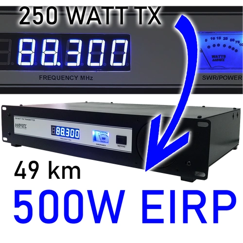
500W EIRP Complete FM Radio Transmitter Broadcasting System

|
5 YEARS
LIMITED WARRANTY |
What Distance Will 49km Do?
If the two way stacked antenna is mounted on a two story building roof, then typical 49km+ can be achieved. If it's mounted on a commercial tower, then 73km+. We can give more accurate predictions on range using satellite elevation data like this RF Coverage Plot at our Facebook page.
PACKAGE CHECKLIST
| Qty | Description | Item |
| 1 | 250W FM Stereo Transmitter with Audio Processing | 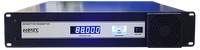 |
| 1 | LMR400 20m / 66ft Cable | 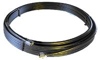 |
| 2 | Standard FM VHF Dipole |  |
| 1 | RF Splitter Boxes | 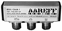 |
| 2 | Mounting Clamps | 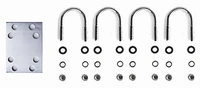 |
250W FM Stereo Transmitter
For the small station, not too small, like a large town, this transmitter is perfect. With 250W clean stereo and legal output. It also has built in audio processing and limiting, so you don't need to provide this separately and this will save you a fortune. Install the antenna then just plug in and go. More info on the 250W Transmitter
The Aareff 'Plug-and-Play' Advantage
| System Component | Engineering Specification | Broadcaster Benefit |
|---|---|---|
| 1W FM Exciter | Internal Veronica PLL Driver | Ultra-low noise, high stability, and zero frequency drift. |
| Audio Processing | Integrated Limiter & Compressor | Prevents illegal over-modulation while ensuring loud, crisp audio. |
| Dynamic RDS | Fully Programmable via USB | Displays your Station Name and Artist info directly on car radios. |
| Antenna & Cable | 0dB Dipole + 12m RG58/CU | 1:1 match guarantees exactly 1W EIRP radiation (No tuning needed). |
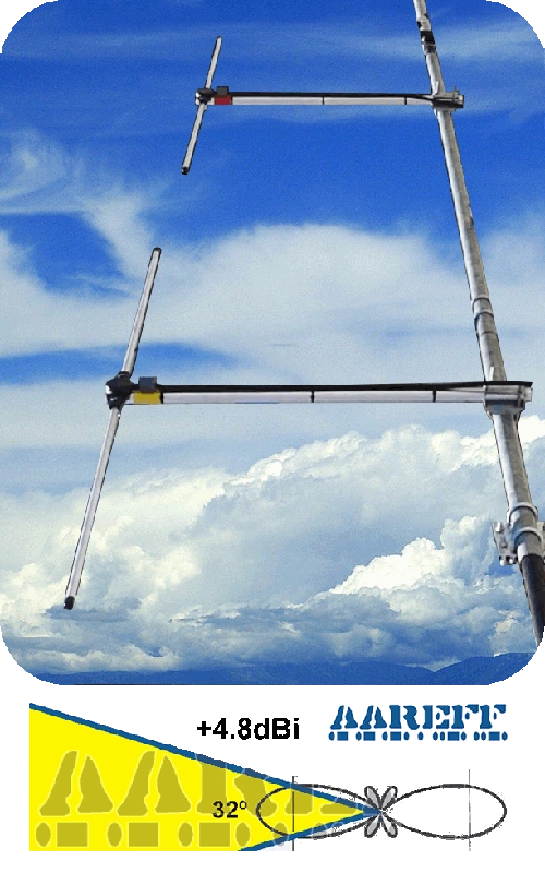
2 Way Stacked Dipole +4.8dBi
The 2 way stacked dipole will provide nearly double the radiated power over a single dipole without any increase in transmitter power. This antenna also covers 88 to 108 MHz without a retune. The 250W transmitter combined with this antenna and 20m of cable produces a radiated output of well over 500W EIRP. More info on the 2 Way Stacked Dipole
20 Metre (66 Feet) Antenna Cable
This package uses 66ft / 20mt of LMR400 antenna cable. The loss on this cable and plus the antenna gain actually results in an EIRP of over 500 watts.

500W Maximum FM Transmission Range Chart: Real-World Listener Data
Understanding Typical Broadcast Coverage
The following range chart is derived from real-world customer reporting, providing a reliable baseline for expected broadcast coverage. This data reflects the typical distances recorded by professional and community stations utilizing our 1W EIRP systems.
- Data Source: Based on average customer signal reports across various geographical environments.
- Verification: Reports are compiled from direct listener communication (phone, text, WhatsApp) to radio stations operated by Aareff customers.
- Zero-Failure Promise: Because this system is perfectly impedance-matched (1W Transmitter to 0dB Dipole), it ensures exactly 1W EIRP is radiated, maximizing range without equipment strain.
It is important to understand that FM transmission range is influenced by numerous variables (e.g., terrain, antenna height, atmospheric conditions, local noise floor). For a detailed breakdown of the factors affecting signal propagation, refer to our dedicated guide on FM Transmission Range.
FM Stereo & Processing: Loud, Crisp Broadcast Quality
The Veronica® system is engineered to deliver a high-impact audio signature. Whether you rely on our internal high-performance processing or your own external rack equipment, our architecture ensures absolute signal integrity.
| Processing Stage | Technical Advantage & Function |
|---|---|
| The Signal Foundation | Utilizes the renowned Veronica® 1W Exciter. This PLL-driven foundation prevents frequency drift and ensures a super-low noise floor for professional carrier integrity. |
| Internal Audio Chain | Includes an Internal Stereo Coder for wide separation and a Dynamic Audio Processor. These boards apply precise limiting and compression to deliver a 'loud and crisp' commercial sound. |
| Professional Bypass | Engineered for flexibility. The internal limiter and stereo coder can be completely disabled to accommodate external processors such as Orban, Inovonics, or PC-generated MPX/RDS signals. |
| Chief Engineer Control | Allows the station's engineering team to maintain their specific 'processing signature' by providing a transparent path for the external MPX baseband signal. |
Do You Have A Question?
DECLARATION OF CONFORMITY
European Union
We hereby declare that this equipment complies with;
• ETS 300384 European Telecommunications Harmonised Standard when used with an audio compressor limiter supplied and tested by Aareff
• EN 301489-11 V1.3.1 (2006-05) EMC Electromagnetic Compatibility when used with 1 meter AC mains cord supplied. If the installation engineer needs to extend this cord, this and the audio input cable should be no more than 3 meters in length to remain in compliance with EMC directive.
• 2006/95/EC Directive (2006-12) LVD Low Voltage Directive.
Equipment compliance is possible using equipment from and in conjunction from other manufacturers, but since this is beyond the control of Aareff Systems, Aareff Systems cannot or be expected to guarantee compliance in this situation.
United States
The following list are the FCC technical requirements for FM broadcasting. We confirm and verify that this transmitter complies with the technical requirements.
47 CFR Chapter I Federal Communications Commission sections:
• 73.1560, 2.1046 RF Power
• 73.1545, 2.1055 Frequency Stability
• 73.317, 2.1049 (e)(3) Emission Limitation, Emission Mask
• 73.317, 2.1057, 2.1051 Emission Limits, Spurious Emissions at Antenna Terminal
• 73.317, 2.1057, 2.1053 Emission Limits, Field Strength of Spurious Emissions


