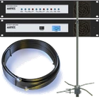
10kW EIRP Complete FM Radio Transmitter Broadcasting System

How Far Will 10kW Reach?
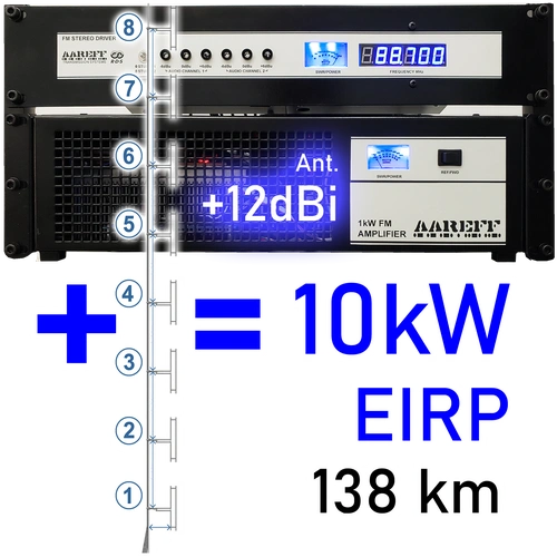
10000W EIRP is a formidable power level, this is just over 6kW ERP which is the power level required by the FCC for a class B1 and C3 stations. You can calculate EIRP and ERP along with antenna gain online here. According to our customer reports distances of up to 138km have been achieved in some directions using 10kW EIRP. In reality on average terrain with average quality radio receivers the normal usable distance would be about half this. For more accurate distance predictions we can make you a radiation plot using satellite elevation data like these
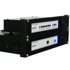
1kW FM Stereo Transmitter
For the small station, not too small, like a large town, this transmitter is perfect. With 1000W clean stereo and legal output. It also has built in audio processing and limiting, so you don't need to provide this separately and this will save you a fortune. Install the antenna then just plug in and go. More info on the 1000W Transmitter
2 dBi Antenna Gain: The Key to Long-Range FM Transmission
System Importance & Key Specifications
The antenna system is the most critical component for maximizing range, directly dictating signal coverage.
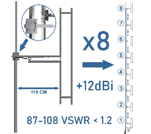
• Antenna Type: Uses eight optimally spaced folded dipoles.
• Achieved Gain: Produces 12 dBi of antenna gain.
• Resulting Power: This gain effectively multiplies the signal pointing to the horizon by 15.85 times (due to 12 dBi), resulting in a massive EIRP transmission signal.
Antenna length, shape, installation, and height are the primary factors determining signal reach (tens of miles vs. less than one mile). A high-gain antenna is essential for achieving long-range FM coverage.
8-Way Folded Dipole Antenna: 12 dBi Gain & High Bandwidth
The antenna system is the most critical component for maximizing range, directly dictating signal coverage.
• Gain: Achieves 12 dBi antenna gain.
• VSWR: Ultra-low SWR of less than 1.2 across the entire 87.5 MHz to 108 MHz band.
• Impact: Magnifies the signal over 15 times for maximum range.
• Durability: Built from aluminum and stainless steel (corrosion-resistant for coastal areas).
12 dBi Gain, Eight Antennas: Calculating Effective Isotropic Radiated Power (EIRP)
Antenna Power Multiplication
This eight-way antenna transforms transmitter power by over 10 times to the final EIRP, even after cable losses.
• EIRP Definition: The signal radiated is Effective Isotropic Radiated Power (EIRP).
• Significance: The signal voltage at the horizon is effectively identical to a much higher-powered transmitter using a single dipole.
The power is effectively identical, hence the name Effective Isotropic Radiated Power (EIRP).
Includes RDS (Radio Data System)
RDS is now included on all stereo transmitters with audio processing. RDS shows your station name and more scrolling across the car radio display.
This RDS is not just ordinary RDS, it is fully programmable dynamic RDS. This means the transmitter can be connected to a PC by a USB cable. The transmitters RDS circuit can be programmed to pick the Artist and Song name from any folder on the PC disk drive. This folder is easy to set up in the DJ playout software, like Zara Studio etc.
-500.webp)
Do You Have A Question?
PACKAGE CHECKLIST
| Qty | Description | Item |
| 1 | FM Stereo Driver with Audio Processing |  |
| 1 | 1000W FM Power Amplifier |  |
| 1 | LMR400/600 40m /131ft Cables | 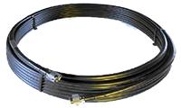 |
| 1 | All Other Connecting Cables |  |
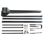
| 8 | Broadband High Power Folded Dipole Antenna with Tower Mounting Clamps and RF Splitters | 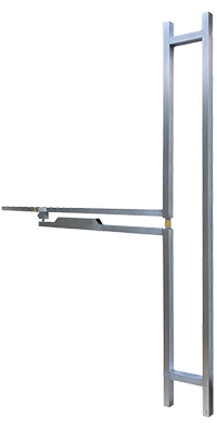 |

|
LIMITED WARRANTY |
40 Meter (130 Feet) LMR-600 Coaxial Antenna Cable: Ultra-Low Loss and High-Gain Performance
This section details the specifications of our LMR-600 coaxial antenna cable, a critical component chosen to ensure maximum power transfer efficiency and signal integrity in professional FM broadcast systems.
Expert-Grade Specifications for Minimal Signal Loss.
Utilizing LMR-600 cable is paramount to achieving specified EIRP levels. Its super low loss characteristics ensure that the maximum power generated by the amplifiers reaches the antenna stack.
• Cable Type: LMR-600 Coaxial Antenna Cable.
• Length: 40 Meters (130 Feet).
• Loss Performance: Exceptional -1 dB of loss over the entire 40-meter run (tested at 100 MHz).
• Efficiency Benefit: This minimal signal loss guarantees that most of the power developed by the amplifiers is transferred with ease to the huge gain antenna stack, preventing wasted energy.
Robust Construction and High-Powered Termination.
The physical characteristics and professional termination of the cable contribute directly to its reliability and longevity:
• Durability: The cable is designed to be robust yet flexible, simplifying installation while ensuring long-term resistance to environmental stress.
• Physical Dimensions: External diameter of approximately 13mm / 0.5 inch.
• Connectors: Both ends are factory-fitted with high-quality, high-powered Teflon DIN7-16 connectors, which are essential for maintaining the low-loss integrity and safe operation at high power levels.
40m (130 Ft) LMR-600 Coaxial Cable: Low-Loss & High-Power
Professional Antenna Connectivity.
Our 40 meter (130 feet) antenna cables utilize high-quality, low-loss LMR-600 foam coaxial cable for optimal signal integrity. This configuration ensures peak performance:
• Function: Connects each amplifier output to the high-powered folded dipole antennas.
• Connectors: 40 Meters (130 Feet).
• Loss Performance: Terminated with robust, high-power 7-16 DIN connectors.
Flexible Length Options & Pricing.
We accommodate specific installation requirements for expert broadcasters:
• Custom Lengths: If you require lengths greater than 40 meters (40m), custom runs are available.
• Pricing: A small extra cost applies for longer runs. Simply contact us for a message with the price and proforma invoice.
40m (130 Ft) LMR-600 Coaxial Cable: Flexible Options & Low Loss
LMR-600 Specifications and Performance.
The standard 40-meter (130 ft) run of LMR-600 coaxial cable is chosen for its high specification and efficiency:
• Low-Loss Guarantee: Features just over a fraction of 1dB loss for 40mt at 100MHz, ensuring minimal power waste.
• Default Cable Type: The supplied cable is robust yet flexible, significantly easing the installation process.
Customization and Length Flexibility.
We offer options to meet specific installation needs and professional preferences:
• Rigid Cable Preference: If your installation requires a more rigid cable type, we can change the system upon request at no extra charge.
• Extra Length: If 40m is not sufficient in length, we will provide a quote for the additional length at a small cost.

10kW Maximum FM Transmission Range Chart: Real-World Listener Data
Understanding Typical Broadcast Coverage.
The following range chart is derived from real-world customer reporting, providing a reliable baseline for expected broadcast coverage. This data reflects the typical ranges really ever recorded by stations utilizing this 100kW EIRP system.
• Data Source: Based on average customer reports in some directions.
• Verification: Reports are primarily compiled from direct listener communication (phone, text, WhatsApp, etc.) to radio station programs operated by our customers.
It is important to understand that FM transmission range is very difficult to predict precisely due to numerous influencing variables (e.g., terrain, antenna height, atmospheric conditions, local noise floor). For a detailed breakdown of the factors affecting signal propagation, refer to our dedicated page FM Transmission Range
FM Stereo Audio and Processing: Achieving Loud, Crisp Broadcast Quality
THE SIGNAL FOUNDATION: LOW NOISE AND HIGH STABILITY
The high-quality FM signal begins with the internal Veronica PLL (Phase-Locked Loop) driver, which serves as the 1W Exciter.
• Function: Produces a super low noise and highly stable FM signal.
• Trustworthiness: Using a trusted PLL driver is fundamental to preventing drift and ensuring carrier integrity, a hallmark of professional-grade equipment.
• Resource: More information on this core component can be found in our 1W Exciter (PLL driver)
INTERNAL AUDIO PROCESSING FOR LISTENERS
After the PLL generates the stable carrier, the internal processing boards take over to shape the audio for the best listener experience:
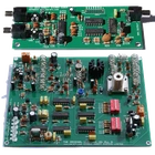
1. Internal Stereo Coder: Generates the FM stereo signal.
2. Internal Audio Processor: Applies dynamic processing (like limiting and compression) to ensure a loud and crisp audio signal on the listener's radio.
PROFESSIONAL FLEXIBILITY: EXTERNAL PROCESSOR INTEGRATION
For expert broadcasters who utilize specialized external equipment, our system offers complete bypass capabilities.
• Integration: If you are an audio professional preferring an external processor (such as Orban, Inovonics, or PC-generated MPX/RDS signals), the system is fully flexible.
• Bypass Capability: The internal limiter, stereo coder, and audio processor boards can be completely disabled.
• Benefit: This flexibility ensures that the signal chain meets the exact, precise specifications and processing signature required by the station's chief engineer.
DECLARATION OF CONFORMITY
European Union
We hereby declare that this equipment complies with;
• ETS 300384 European Telecommunications Harmonised Standard when used with an audio compressor limiter supplied and tested by Aareff
• EN 301489-11 V1.3.1 (2006-05) EMC Electromagnetic Compatibility when used with 1 meter AC mains cord supplied. If the installation engineer needs to extend this cord, this and the audio input cable should be no more than 3 meters in length to remain in compliance with EMC directive.
• 2006/95/EC Directive (2006-12) LVD Low Voltage Directive.
Equipment compliance is possible using equipment from and in conjunction from other manufacturers, but since this is beyond the control of Aareff Systems, Aareff Systems cannot or be expected to guarantee compliance in this situation.
United States
The following list are the FCC technical requirements for FM broadcasting. We confirm and verify that this transmitter complies with the technical requirements.
47 CFR Chapter I Federal Communications Commission sections:
• 73.1560, 2.1046 RF Power
• 73.1545, 2.1055 Frequency Stability
• 73.317, 2.1049 (e)(3) Emission Limitation, Emission Mask
• 73.317, 2.1057, 2.1051 Emission Limits, Spurious Emissions at Antenna Terminal
• 73.317, 2.1057, 2.1053 Emission Limits, Field Strength of Spurious Emissions

 +1 829 698 0733
What Do You Need? Talk To Us
