+1 829 698 0733
What Do You Need? Talk To Us
+1 829 698 0733
What Do You Need? Talk To Us8am-4pm EST/NY Monday-Friday info@aareff.com

Circular Polarised FM Antenna (Square Cycloid)
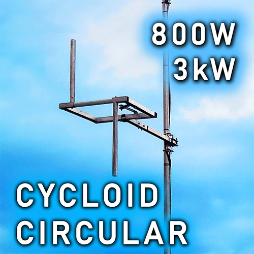
Simple and Compact Design
Despite it's square shape, don't be fooled, this antenna gives true circular polarization exactly the same as a circular shaped antenna would do.
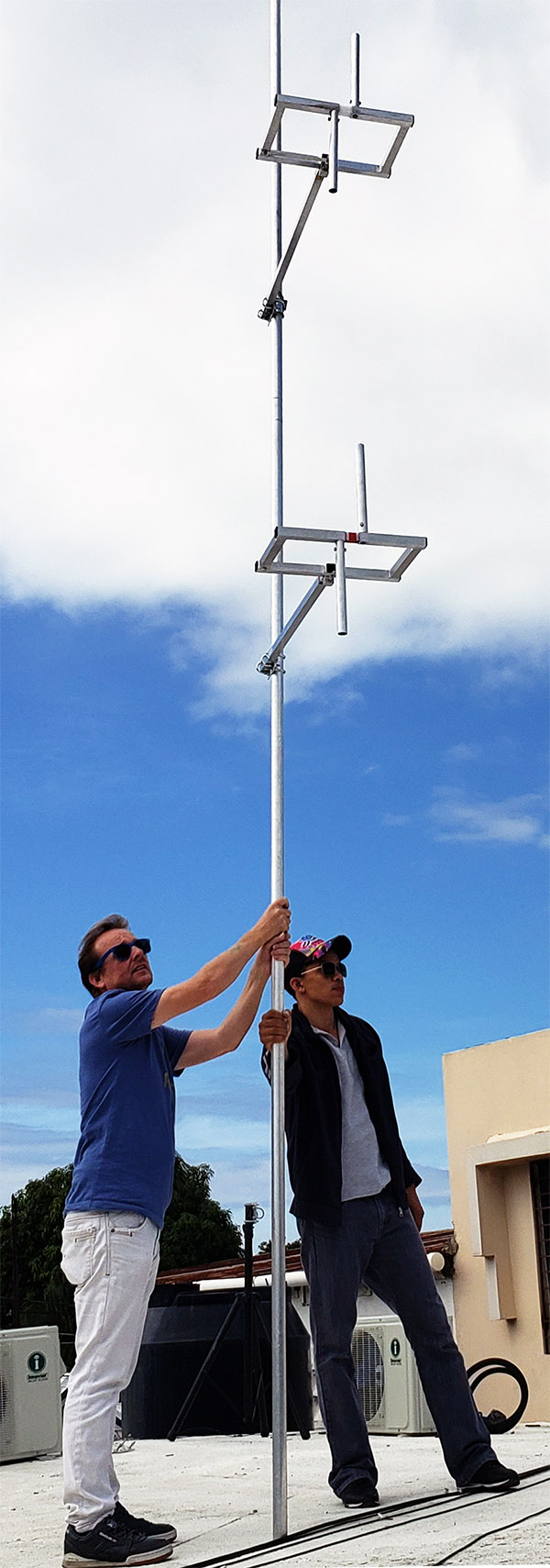
The antenna is a simple, compact design made of lightweight aluminum welded together, not bolted, this means better reliability with aging and no possibility of things getting loose in the wind. It's perfect for countries where the regulator demands circular polarization in the permit or license.
Ideal for low-power broadcast stations up to 800W for the N type versions and up to 3kW for the 7-16 DIN versions.
There are four versions of this antenna, the single, 2 bay, 4 bay and 8 bay with gains shown in the specification table below.
Technical Specification
| Single | 2 Bay | 4 Bay | 8 Bay | |
| 0.5 λ dBd | -3.00 | -1.50 | +1.50 | +4.50 |
| 0.5 λ dBi | -0.85 | +0.65 | +3.65 | +6.65 |
| 0.9 λ dBd | -3.00 | -0.00 | +3.30 | +6.40 |
| 0.9 λ dBi | -0.85 | +1.95 | +5.45 | +8.55 |
| Weight | 2Kg | 5.6Kg | 11Kg | 22Kg |
| Bandwidth (SWR 1.5) | +/- 2.8 MHz |
| Impedance | 50 ohm |
| SWR at Tuned Frequency | <1.2 |
| Max. Power N Connector | 800W |
| Max. Power 7-16 Connector | 3kW |
| Construction | Aluminium, Stainless Steel and Teflon |
Click here for User Manual
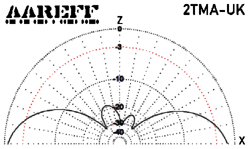
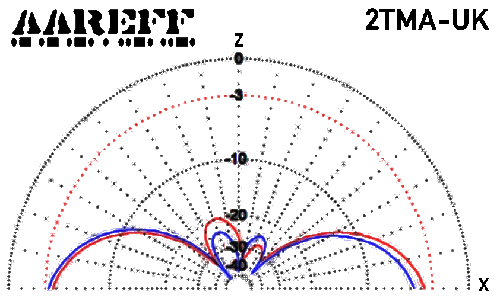
The radiation plots and picture shown in this page are for the 2 bay version. Contact us if you require plots for the single, 4 and 8 bay versions
The price panel below shows the N connector versions which are all rated at 800W and the 3kW versions using 7-16 DIN connectors.
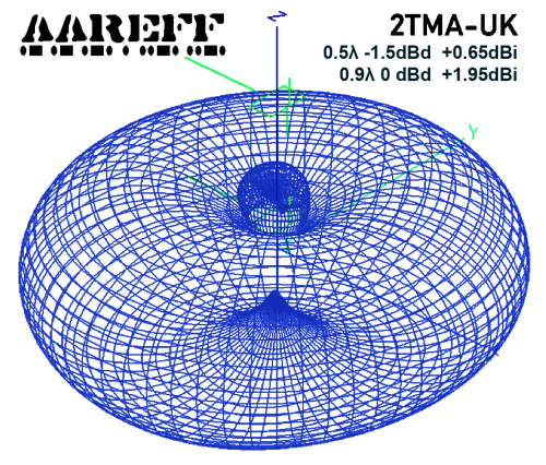
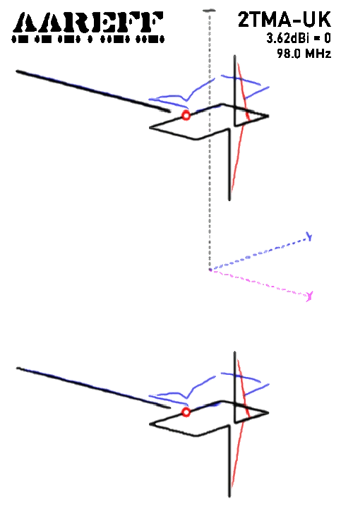
3D COMBINED TOTAL PATTERN
This is the combined horizontal and vertical polarization pattern of the 2 bay version with 0.5λ vertical spacing. Note that the 'End Fire', this is the lobe shooting out of the top straight up vertically is -19dB relative to the maximum gain. If you look carefully at the bottom you can also see the indent, this clearly shows no straight down end fire.
This is important for the FCC in the United States and Ofcom in the United Kingdom, both regulators in some locations stipulate that stacked circular antennas must have less than 20dB end fire. This is to prevent downwards radiation directly under the tower being danger to personnel and also upwards radiation above the tower potentially causing saturation or overload of aircraft communications systems. So the 2 bay (and also 4 and 8 bay) with vertical spacing of 0.5λ is perfect to remain legal and compliant with these rules.
If the spacing is set at 0.9λ then an additional gain of +1.5dB can be achieved, however end fire with large lobes will occur.
Do You Have A Question?
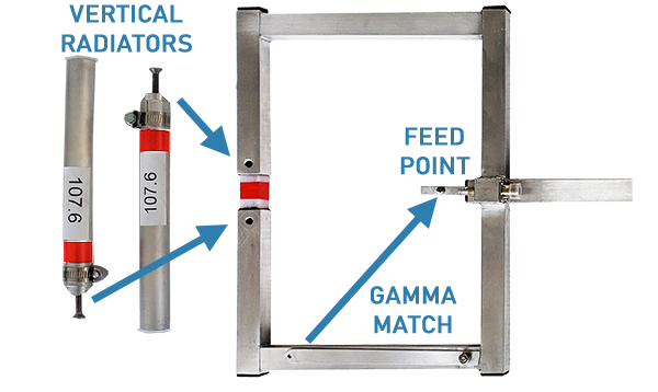
ASSEMBLING THE CYCLOIDS
Whether it's the two bay, four bay or eight bay antenna system, each Cycloid Dipole is easy to assemble.
As you can see in the picture below, each Cycloid Dipole is delivered in three pieces, the main body and the two vertical radiators.
Assembly is a breeze. 1. Simply attach and screw tight the vertical radiators to the main body and then 2. Swing the Gamma Match across and screw it to the feed point.
The antenna is now ready for mounting to the tower, pole or mast and connecting to the coaxial splitter cable supplied.
You can find the full installation instructions here
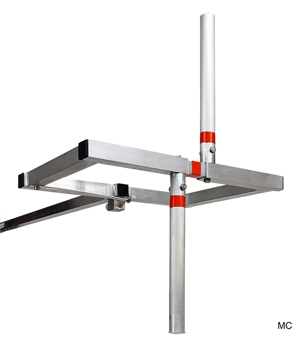
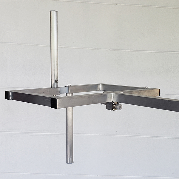
FRONT AND BACK VIEW
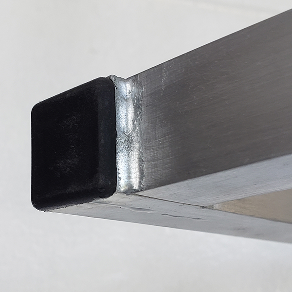
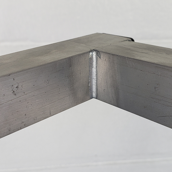
ALUMINIUM WELDED
ANTENNA GEOMETRY
H PLANE VERT. AND HOR.
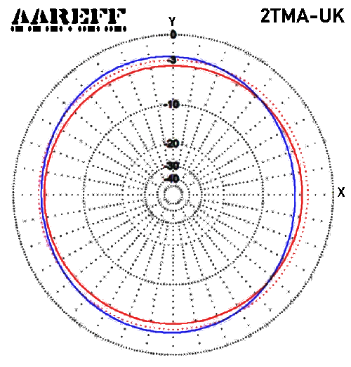
H PLANE COMBINED TOTAL
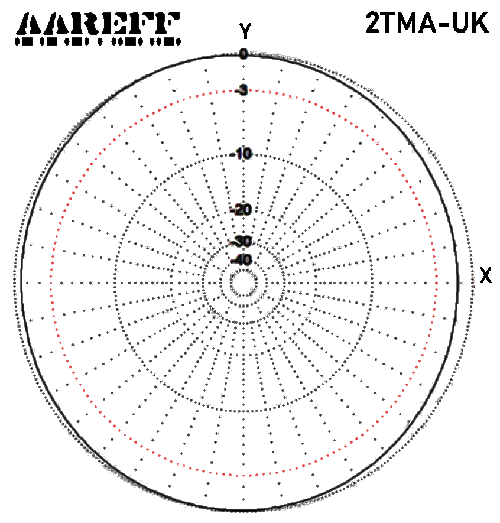
E PLANE VERT. AND HOR.
E PLANE TOTAL