8am-4pm EST/NY Monday-Friday info@aareff.com

User Manual and Installation of 2 Way Circular Antenna
 IMPORTANT!
The antenna is the most important part of the transmission system and must be correctly installed before proceeding further and before any transmission equipment is connected.
Under no circumstances should the antenna be mounted and used at ground level or within a few meters of personnel.
Ideally this antenna should be mounted at least 20 meters high and clear of any surrounding objects to get maximum range and more importantly to reduce risk of radio frequency radiation to personnel. When mounted at least 20 meters in height off ground and using 400 watts of transmitter power, power flux density measurements made at ground level directly under the antenna show less than 1 W/m2. Several European countries use a value for the power flux density of 10 W/m2 as a basis for considering whether or not an area is safe. The issue of radio frequency radiation limits is a contentious one and work in this field is continuing worldwide.
You are responsible for selecting the correct antenna for your application, installing it properly and ensuring the system maintenance.
PARTS LAYOUT
| Qty | Item |
| 2 | A. Cycloid (square) main dipole with RF connector and Teflon / fiberglass support |
| 4 | B. Vertical radiator with one M6 screw x 50mm, one M6 washer and one M6 spring washer |
| 2 | C.
Joining clamps with: 4 x M6 x 40mm screw 8 x M6 washers 4 x M6 spring washers 4 x M6 nuts |
| 2 | D. Boom extension |
| 2 | E.
Tuning arm / gamma match bars with: 1 x M4 Allen head screw 2 x M4 washers 1 x M4 nut 2 x M6 x 40mm screws 4 x M6 washers 2 x M6 spring washers 2 x M6 nuts 10mm aluminum sleeve |
| 2 | F.
Mast fixing clamps with: 2 x U-bolts 4 x M8 washers 4 x M8 spring washers 4 x M8 nuts 4 x M6 x 50mm screws 8 x M6 washers 4 x M6 spring washers 4 x M6 nuts |
| Qty | Item |
| 1 | G. Splitter box with three N-female connectors |
| 1 | H. RED Splitter Cable LMR400 + 63cm RG11 |
| 1 | I. YELLOW Splitter cable LMR400 + 63cm RG11 |
NEAR POWER LINES
Following is a list of precautions to follow when installing the antenna if placement of antenna and cables is anywhere near power lines.
- Erect antenna on side of house or building as far away as possible from the power line.
- Avoid crossing antenna cables under electrical power lines.
- Do not attach antennas to towers, poles or similar structures carrying electrical power lines.
- If you are not experienced in installation of antennas, have experienced persons assist you.
- During installation, tie off antenna with rope so if it falls it can be diverted away from power lines.
- Avoid fastening antennas, especially self-supporting types, to old chimneys or to any chimney not designed to take such stress. Forces created by a strong wind may be sufficient to topple both chimney and antenna.
- Make sure antennas have been properly grounded and provided with other necessary lightning protection.
INTENDED USE
This antenna is intended for use with an FM broadcasting transmitter up to 800 watts at a permanently pre-defined location with a license or authorisation from the radio spectrum regulator of your country.
TOOLS YOU WILL NEED
- PVC insulation tape and/or Self Amalgamating Tape
- Metric Tape Measure
- 7mm, 10mm, 13mm Spanner
- Allen key 3mm
ASSEMBLY - CYCLOID DIPOLES
Assemble the four cycloid dipoles exactly as shown in the image above. Make sure the spring washer and plain washer are used together, next to one and other, and tightened, this will prevent the screws working loose in the wind.
For best performance, all the pieces marked with '1' should go with each other, then '2', '3' and '4'. This is the way and order they were tested at our factory.
ASSEMBLY - BOOM EXTENDER
Take A the main cycloid and join it to D the boom extension using C joining clamps and the four M6 screws and washers. Make sure the spring washer and plain washer are used together, next to one and other, and tightened, this will prevent the screws working loose in the wind.
The image shows the RED cable with the 90 degree connector to the cycloid antenna. In total there are two YELLOW cables and two RED cables each with 90 degree connectors. Connect these four cables to the four cycloid antennas as shown in the image. You should end up with two cycloid antennas with RED cables and two with YELLOW cables.
ASSEMBLY - MAST CLAMP
Using the parts marked F (Mast Clamps) assemble the mast clamp as shown in this photo. Make sure the spring washer and plain washer are used together, next to one and other, and tightened, this will prevent the screws working loose in the wind.
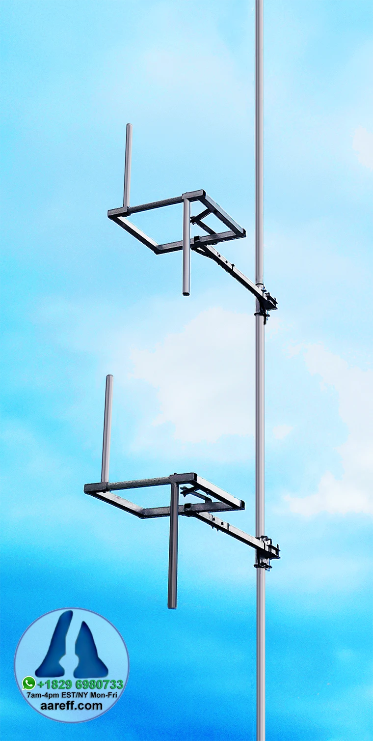
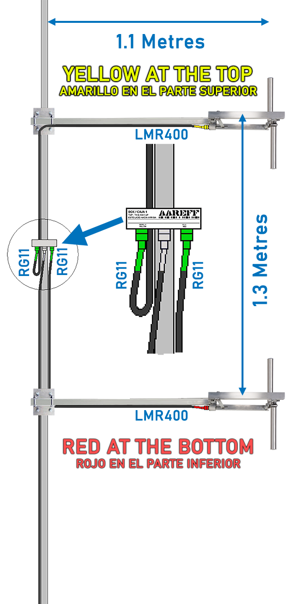
MAIN ASSEMBLY PLAN
MAIN ASSEMBLY INSTRUCTIONS
1. Mount the cycloid dipoles to the mast using the clamps provided in this order:
ANT.1 - YELLOW at the top
ANT.2 - RED at the bottom.
It is IMPORTANT for correct operation that this order of RED and YELLOW is followed
It is also important the dimensions on the diagram are followed as closely as possible, the cycloid dipoles must be directly above each other for the system to work properly and give the full tuned bandwidth of +/- 2.8 MHz (SWR <1.5).
2. Mount the splitter box using the tie wraps provided to the mast as shown in the diagram between ANT.1 and ANT.2
The connectors on the splitter box should be facing down. This is because the body of the splitter box shelters, not fully, but a little, the connections from rain and water
3. Connect the main feeder cable from the transmitter to the CENTER connector of the splitter box.
4. Connect the YELLOW cable from ANT.1 to the outer connector of splitter box
5. Connect the RED cable from ANT.2 to the remaining outer connector of splitter box
IT'S VERY IMPORTANT THAT THIS COLOUR CODE IS FOLLOWED EXACTLY OR THE ANTENNA WILL NOT WORK
6. Wrap PVC or Self Amalgamating tape tightly around and all over the plugs on the splitter box to waterproof them.
7. Securely fix the cables using PVC tape or large cable ties to the mast as shown in the diagram opposite. Make sure the cables are not going to flap around in the wind.
8. Make sure that all fixings are tight and are not going to work loose over time with wind.
3D COMBINED TOTAL PATTERN
ANTENNA GEOMETRY
H PLANE VERT. AND HORI.
H PLANE TOTAL
E PLANE VERT.AND HORI.
E PLANE TOTAL
SPECIFICATION AND DESIGN
| Gain | 3.62dBi / 1.47dBd at 98MHz |
| Freq Range | 87.5 to 108 MHz (Factory Tuned) |
| Bandwidth | 2.8 MHz |
| SWR | 1.5 max |
| Max Power | 800 Watts |
| Construction | Aluminium, Teflon, Resin and Stainless Steel |
| Connector | N type Female |
| Input Z | 50 ohm unbalanced |
| Polarization | Circular / Mixed |
| Vertical Beamwidth | 32 Degrees |
| Weight | 5.6 Kg |
EM COMPATIBILITY
When writing this manual there was no EU directive regarding the EMC (Electro Magnetic Compatibility) of Band II VHF broadcast antennas, however in our view there are some potential EMC compatibility issues that need to be addressed when installing this antenna system. On completion of the antenna installation check;
1. All the cables entering the connectors are tight and properly crimped or soldered
2. All the connectors are screwed in tight and sound.
3. PVC insulation tape and/or self amalgamating tape are wrapped around all the connectors to stop water entering the connector and the inside of the body of the cable.
If any cables are loose or there are bad connections this can cause some non-linear resistance, diode action or some small arcing. When this happens it creates EMC disturbance (arcing and crackling sound) across a wide frequency spectrum.
MAINTENANCE
Because antennas are passive devices maintenance requirements are low, however don’t accept low as being none existent, some periodic inspections are required.
Always following a heavy storm or extreme weather condition an inspection should be done and as shown in the table below.
| WEEKS | Building Roof | Light Duty Tower | Heavy Duty Tower |
| 13 |  |
||
| 26 | |
|
|
| 39 | |
||
| 52 | |
|
|
LEGAL ADVICE
We sell this equipment to professionals and organizations in good faith it will be used correctly and legally. Most countries in the world require licensing for this antenna to be used with a transmitter. It is the customer’s responsibility to check relevant laws, directives, regulations and licensing requirements before putting this product into service with an antenna system. You, the customer or user agree to defend, indemnify and hold harmless Aareff Systems Limited, its employees and agents, from and against any claims, actions or demands, including without limitation legal and accounting fees, alleging or resulting from improper or unlawful use of this equipment.
© 2020 AAREFF SYSTEMS LIMITED
ALL RIGHTS RESERVED. Aareff is a trademark of Aareff Transmission Systems. All contents of this document including, but not limited to the images, logos, text, illustrations are protected by copyrights, trademarks and other intellectual property rights which are owned and controlled by Aareff Transmission Systems or by other parties that have licensed their material to Aareff Transmission Systems. This document in part or whole may not be copied, reproduced, republished, uploaded, posted or distributed in any way, including by e-mail, ftp or any other electronic means
Every care has been taken in the preparation of this document, errors in content, typographical or otherwise, may have occurred. If you have comments concerning its accuracy, please contact Aareff Systems Limited (UK)


