8am-4pm EST/NY Monday-Friday info@aareff.com

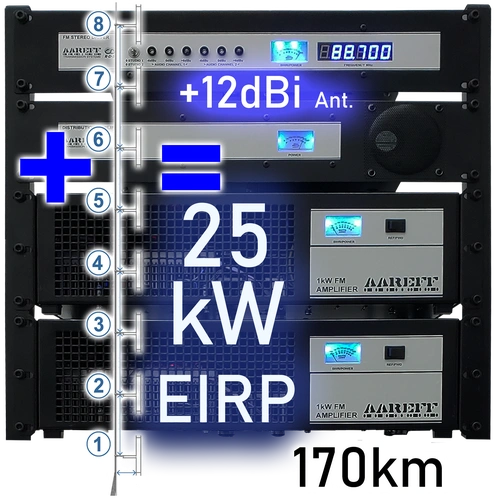
25kW EIRP Complete FM Radio Transmitter Broadcasting System

|
5 YEARS
LIMITED WARRANTY |
How Far Will 25kW Reach?
On open rural land with good antenna height you can expect 25kW EIRP to reach 170km, maybe a little more. In a dense city like New York with tall buildings made of steel and concrete, this would cause great attenuation to the signal and reduce the coverage area by 10 times, you could expect only a few miles. So, the transmission distance really depends on many factors. If you send us the GPS coordinates of your antenna site and the antenna height, we can make a plot of you using satellite elevation data of where the signal can be received. We have a great example of this HERE
PACKAGE CHECKLIST
| Qty | Description | Item |
| 1 | FM Stereo Driver with Audio Processing |  |
| 1 | Distribution Splitter Amplifier |  |
| 2 | 1000W FM Power Amplifier | 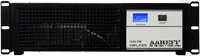 |
| 2 | LMR600 40m /131ft Cables | 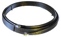 |
| 1 | All Other Connecting Cables |  |
| 8 | Broadband High Power Folded Dipole Antenna with Tower Mounting Clamps | 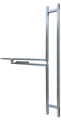 |
2kW FM Transmitter Power
To achieve 25kW EIRP only 2kW of FM transmitter power is needed if the correct antenna is installed with high grade coaxial cable. The 2kW of FM transmitter power comes from 2 separate 1kW amplifiers that are driven by a distribution amplifier and Veronica® 1W PLL driver. All our big systems above 10kW EIRP are configured this way using more than just a single 1kW amplifier. Due to this a complete shutdown or signal failure can only occur if the 2 amplifiers (1kW each) go down at exactly the same time, this is nearly impossible with super high odds. So if you need system reliability and a station on air, always, with no breakdowns, 2 or more if possible, 1kW amplifiers are perfect.
Achieving 2kW FM Transmitter Power
Achieve Maximum Reach: 100kW Effective Isotropic Radiated Power (EIRP) with Only 2kW FM Transmitter Power
This section details how to achieve a powerful 100kW EIRP while utilizing only 8kW of FM transmitter power, emphasizing system reliability and professional design.
Key Component Requirements for 100kW EIRP
Achieving optimal signal strength requires a strategic combination of high-quality components, minimizing the required FM transmitter power:
•FM Transmitter Power: Only 2kW is required.
•Antenna System: Installation of the correct, high-gain antenna.
•Transmission Line: Utilization of high-grade coaxial cable.
System Architecture for High-Power FM Broadcasts.
Our large-scale FM transmission systems, particularly those configured for 10kW EIRP and above, are engineered for maximum performance and stability. The standard configuration for the 8kW FM Transmitter utilizes a highly robust, modular design:
Individual Amplifiers:
•Quantity: 8 Separate Units.
•Power/Function: 1kW each.
•Benefit: Redundancy and Reliability.
Driver:
•Quantity: 1.
•Power/Function: Distribution Amplifier.
•Benefit: Signal Distribution.
PLL Driver:
•Quantity: 1.
•Power/Function: Veronica® 1W PLL
•Benefit: Precise Frequency Control.
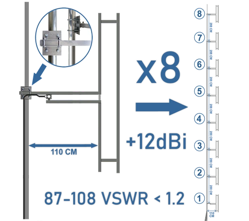
2 dBi Antenna Gain: The Key to Long-Range FM Transmission
System Importance & Key Specifications
The antenna system is the most critical component for maximizing range, directly dictating signal coverage.
• Antenna Type: Uses eight optimally spaced folded dipoles.
• Achieved Gain: Produces 12 dBi of antenna gain.
• Resulting Power: This gain effectively multiplies the signal pointing to the horizon by 15.85 times (due to 12 dBi), resulting in a massive EIRP transmission signal.
Antenna length, shape, installation, and height are the primary factors determining signal reach (tens of miles vs. less than one mile). A high-gain antenna is essential for achieving long-range FM coverage.
40m (130 Ft) LMR-600 Coaxial Cable: Flexible Options & Low Loss
LMR-600 Specifications and Performance.
The standard 40-meter (130 ft) run of LMR-600 coaxial cable is chosen for its high specification and efficiency:
• Low-Loss Guarantee: Features just over a fraction of 1dB loss for 40mt at 100MHz, ensuring minimal power waste.
• Default Cable Type: The supplied cable is robust yet flexible, significantly easing the installation process.
Customization and Length Flexibility.
We offer options to meet specific installation needs and professional preferences:
• Rigid Cable Preference: If your installation requires a more rigid cable type, we can change the system upon request at no extra charge.
• Extra Length: If 40m is not sufficient in length, we will provide a quote for the additional length at a small cost.

25kW Maximum FM Transmission Range Chart: Real-World Listener Data
Understanding Typical Broadcast Coverage
The following range chart is derived from real-world customer reporting, providing a reliable baseline for expected broadcast coverage. This data reflects the typical distances recorded by professional and community stations utilizing our 1W EIRP systems.
- Data Source: Based on average customer signal reports across various geographical environments.
- Verification: Reports are compiled from direct listener communication (phone, text, WhatsApp) to radio stations operated by Aareff customers.
- Zero-Failure Promise: Because this system is perfectly impedance-matched (1W Transmitter to 0dB Dipole), it ensures exactly 1W EIRP is radiated, maximizing range without equipment strain.
It is important to understand that FM transmission range is influenced by numerous variables (e.g., terrain, antenna height, atmospheric conditions, local noise floor). For a detailed breakdown of the factors affecting signal propagation, refer to our dedicated guide on FM Transmission Range.
FM Stereo & Processing: Loud, Crisp Broadcast Quality
The Veronica® system is engineered to deliver a high-impact audio signature. Whether you rely on our internal high-performance processing or your own external rack equipment, our architecture ensures absolute signal integrity.
| Processing Stage | Technical Advantage & Function |
|---|---|
| The Signal Foundation | Utilizes the renowned Veronica® 1W Exciter. This PLL-driven foundation prevents frequency drift and ensures a super-low noise floor for professional carrier integrity. |
| Internal Audio Chain | Includes an Internal Stereo Coder for wide separation and a Dynamic Audio Processor. These boards apply precise limiting and compression to deliver a 'loud and crisp' commercial sound. |
| Professional Bypass | Engineered for flexibility. The internal limiter and stereo coder can be completely disabled to accommodate external processors such as Orban, Inovonics, or PC-generated MPX/RDS signals. |
| Chief Engineer Control | Allows the station's engineering team to maintain their specific 'processing signature' by providing a transparent path for the external MPX baseband signal. |
Do You Have A Question?
DECLARATION OF CONFORMITY
European Union
We hereby declare that this equipment complies with;
• ETS 300384 European Telecommunications Harmonised Standard when used with an audio compressor limiter supplied and tested by Aareff
• EN 301489-11 V1.3.1 (2006-05) EMC Electromagnetic Compatibility when used with 1 meter AC mains cord supplied. If the installation engineer needs to extend this cord, this and the audio input cable should be no more than 3 meters in length to remain in compliance with EMC directive.
• 2006/95/EC Directive (2006-12) LVD Low Voltage Directive.
Equipment compliance is possible using equipment from and in conjunction from other manufacturers, but since this is beyond the control of Aareff Systems, Aareff Systems cannot or be expected to guarantee compliance in this situation.
United States
The following list are the FCC technical requirements for FM broadcasting. We confirm and verify that this transmitter complies with the technical requirements.
47 CFR Chapter I Federal Communications Commission sections:
• 73.1560, 2.1046 RF Power
• 73.1545, 2.1055 Frequency Stability
• 73.317, 2.1049 (e)(3) Emission Limitation, Emission Mask
• 73.317, 2.1057, 2.1051 Emission Limits, Spurious Emissions at Antenna Terminal
• 73.317, 2.1057, 2.1053 Emission Limits, Field Strength of Spurious Emissions


