 +1 829 698 0733
What Do You Need? Talk To Us
+1 829 698 0733
What Do You Need? Talk To Us8am-4pm EST/NY Monday-Friday info@aareff.com

User Manual and Installation of 8000W (8KW) EIRP System
INTENDED USE
i. The various pieces of equipment in this document are only for use permanently at a pre-defined location with a license or authorisation from the radio spectrum regulator in your country or EU member state.
ii. The installer must have competent RF engineering skills at their disposal, be EMC aware and understand radio frequency systems. The final installation should be in accordance with the site engineering document at https://www.aareff.com/ETR132.pdf The radio station management must assign a responsible person to the transmission equipment and installation.
TRANSMITTER PACKAGE CHECKLIST
| Qty | Description | Item |
| 1 | Stereo coder audio limiter / 1 watt FM driver exciter 15V DC (ALSCB & 1WPLLB) |  |
| 1 | Distribution amplifier 15V DC |  |
| 2 | 800W FM power amplifier |  |
| 2 | DC to DC Lead (DC connections from ALSCB to 1WPLLB to distribution amplifier) |  |
| 3 | IEC AC power cord |  |
| 1 | MPX audio lead (audio connection from ALSCB to 1WPLLB) |  |
| 3 | BNC to BNC lead (rf connection from 1WPLLB to Distribution Amplifier to 2 x 800WNTAP) |  |
| 1 | 15V DC switch mode AC power supply (60w) |  |
ANTENNA PACKAGE CHECKLIST
| Qty | Set | Description |
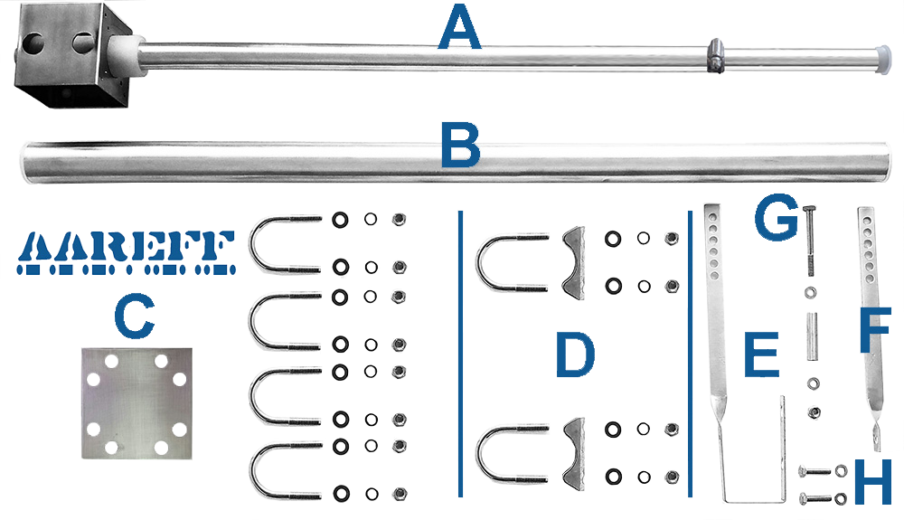
| 4 | A | 1/2 wave, base, 25mm dia. main radiator, 22mm dia. top adjust tube and tube clamp |
| 4 | B | 38mm x 800mm boom tube |
| 4 | C | Boom to mast/ tower mounting clamp. Each set includes, 1 x 100mm square 3.2mm thick clamping plate, 4 x 38mm U bolts with M8 threads, 8 x M8 spring washers, 8 x M8 plain washers and 8 x M8 nuts |
| 4 | D | Antenna base to boom U bolts clamp assemblies. Each set includes 2 x 38mm U bolts with M8 threads, 2 x 38mm tube clamp, 4 x M8 spring washers, 4 x M8 plain washers and 4 x M8 nuts |
| 4 | E | Bottom tuning bar |
| 4 | F | Top tuning bar |
| 4 | G | Tuning bar M6 screw, 1 aluminium sleeve, 2 M6 washers and 1 M6 nut |
| 4 | H | Tuning bar M6 screws and washers |
| Qty | Description | Item |
| 2 | Splitter Boxes | 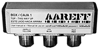 |
| 4 | Combo cable LMR400 (2.93 mt BLUE plug) and RG11 (0.63 mt) GREEN plug, total length 3.56 mt | 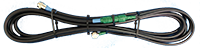 |
| 2 | 30m rolls of LMR400 equal phased antenna cable | 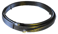 |
 IMPORTANT! PLEASE READ, we know it's boring, but if you want your system to work correctly, safely and legally, it is necessary.
The antenna is the most important part of the transmission system and must be correctly installed before proceeding further and before any other transmission equipment is connected.
Ideally this antenna should be mounted at least 20 meters high and clear of any surrounding objects to get maximum range and more importantly to reduce risk of radio frequency radiation to personnel. When mounted at least 20 meters in height off ground and using 1600 watts of transmitter power, power flux density measurements made at ground level directly under the antenna show less than 1 W/m2. Several European countries use a value for the power flux density of 10 W/m2 as a basis for considering whether or not an area is safe. The issue of radio frequency radiation limits is a contentious one and work in this field is continuing worldwide. Under no circumstances should the antenna be mounted and used at ground level or within a few meters of personnel.
IMPORTANT! INSTALLATION NEAR TO POWER LINES
- Erect antenna on pole, mast or tower as far away as possible from the power lines
- Avoid crossing antenna cables under electrical power lines
- Do not attach antennas to towers, poles or similar structures carrying electrical power lines
- If you are not experienced in installation of antennas, have experienced persons assist you
- During installation, tie off antenna with a rope so if it falls it can be diverted away from the power lines
- Avoid fastening antennas, especially self-supporting types, to old chimneys or to any chimney not designed to take such stress. Forces created by a strong wind may be sufficient to topple both chimney and antenna
ELECTROMAGNETIC COMPATIBILITY
When writing this manual there was no EU directive regarding the EMC compatibility of Band II VHF broadcast antennas, however in our view there are some potential EMC compatibility issues that need to be addressed when installing this antenna system. On completion of the antenna installation check;
- All the cables entering the connectors are tight and properly crimped or soldered
- All the connectors are screwed in tight and sound
- PVC insulation tape and/or self amalgamating tape are wrapped around all the connectors to stop water entering the connector and the inside of the body of the cable
- If any cables are loose or there are bad connections this can cause some non-linear resistance, diode action or some small arcing. When this happens it creates EMC disturbance (arcing and crackling sound) across a wide frequency spectrum
TO ERECT THIS ANTENNA YOU WILL NEED TO PROVIDE
- PVC insulation tape and/or self amalgamating tape
- Metric tape measure at least 3m
- Two 13mm spanners, one with a ringed end
- 10mm socket and wrench
- Flat medium size screwdriver
- A secure mounting mast with a diameter of 38mm (1 1/2 inch) and clear length of at least 13 meters for mounting the dipole antennas to.
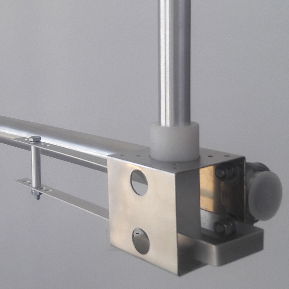
ASSEMBLING THE FOUR HALF WAVE ANTENNA BASE SECTIONS
Using the following items to assemble the four antenna base sections with the tuning loops as shown in the picture below.
1 x (A) 0.5λ (half wave) radiator and base
2 x (D) Antenna base to boom U bolts clamp assemblies
1 x (F) Top tuning bar
1 x (E) Bottom tuning bar
2 x (H) M6 screws and 2 washers
1 x (G) Tuning bar M6 screw, 1 x aluminium sleeve, 2 x M6 washers and 1 x M6 nut
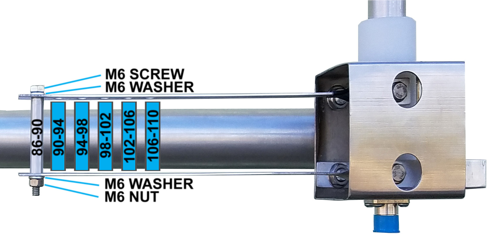
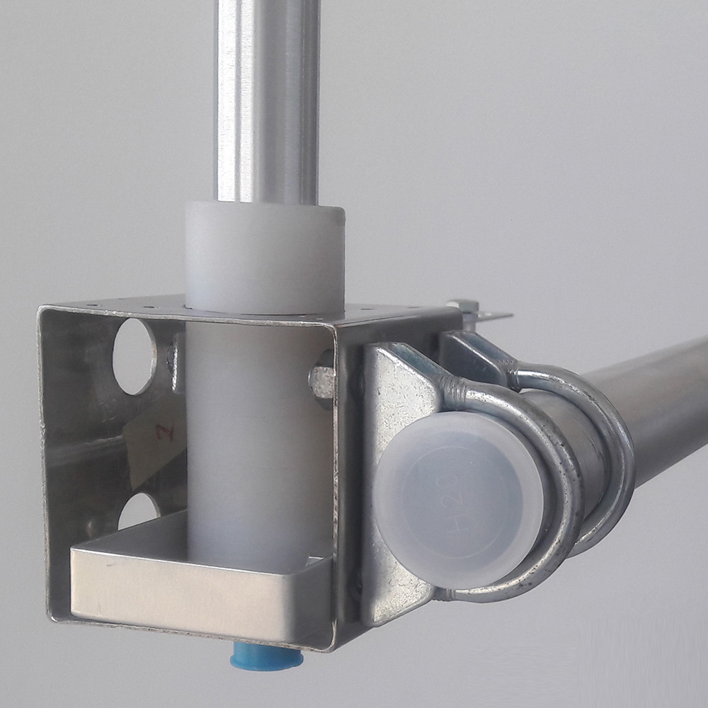
1. The tuning loop, bar and aluminium sleeve form an half turn inductor. The operating frequency determines the position of the aluminium sleeve. Put the aluminium sleeve in one of the six positions shown in picture for the frequency that you want. This sleeve will be carrying a huge RF current, make sure it is tight and firm. The tuning loop and bar should also be screwed tight to the Teflon section with the two M6 screws and washers. This is shown in the pictures.
2. The bottom tuning bar should also be clamped tight to the back plate of the base and the 38mm x 800mm boom tube using the U bolt clamp assemblies. Again as shown in the picture below.
ADJUSTING THE SPACING AND THE LENGTH
Pick the frequency (MHz) from the table that is the closest to frequency you need to use. For example if you needed 91.3 MHz, then you would pick 91 MHz, this is the closest.
1. Adjust the radiator to length shown in metres for 0.5λ (wavelength). Use a metric tape measure to measure the length from the (IMPORTANT) top plate of the base section to the end of the top tube. Slide the top radiator tube inside the bottom large radiator tube until the correct length is reached. At the correct length tighten the circular screw clip to secure the two tubes in place. Make sure the clip is tight and the tubes don't move. DOUBLE check the length again from the top plate of the base section to the end of the top tube. If this length is not correct, the antenna will not radiate correctly and there'll be high reflected power and SWR.
2. Adjust the distance / spacing between the booms for the frequency of 0.9λ (wavelength). This is not a critical measurement and only needs to be accurate to +/- 2 or 3 cm of the length shown in the table. This spacing optimises the complete antenna system to give maximum gain to the horizon.
| FREQ. MHz | 0.9λ Vertical Spacing | 0.5λ Radiator Length |
| 87 MHz | 3.10 mt | 1.64 mt |
| 88 MHz | 3.07 mt | 1.62 mt |
| 89 MHz | 3.03 mt | 1.60 mt |
| 90 MHz | 3.00 mt | 1.58 mt |
| 91 MHz | 2.97 mt | 1.57 mt |
| 92 MHz | 2.93 mt | 1.55 mt |
| 93 MHz | 2.90 mt | 1.53 mt |
| 94 MHz | 2.87 mt | 1.52 mt |
| 95 MHz | 2.84 mt | 1.50 mt |
| 96 MHz | 2.81 mt | 1.48 mt |
| 97 MHz | 2.78 mt | 1.47 mt |
| FREQ. MHz | 0.9λ Vertical Spacing | 0.5λ Radiator Length |
| 98 MHz | 2.76 mt | 1.45 mt |
| 99 MHz | 2.73 mt | 1.44 mt |
| 100 MHz | 2.70 mt | 1.43 mt |
| 101 MHz | 2.67 mt | 1.41 mt |
| 102 MHz | 2.65 mt | 1.40 mt |
| 103 MHz | 2.62 mt | 1.38 mt |
| 104 MHz | 2.60 mt | 1.37 mt |
| 105 MHz | 2.57 mt | 1.36 mt |
| 106 MHz | 2.55 mt | 1.34 mt |
| 107 MHz | 2.52 mt | 1.33 mt |
| 108 MHz | 2.50 mt | 1.32 mt |
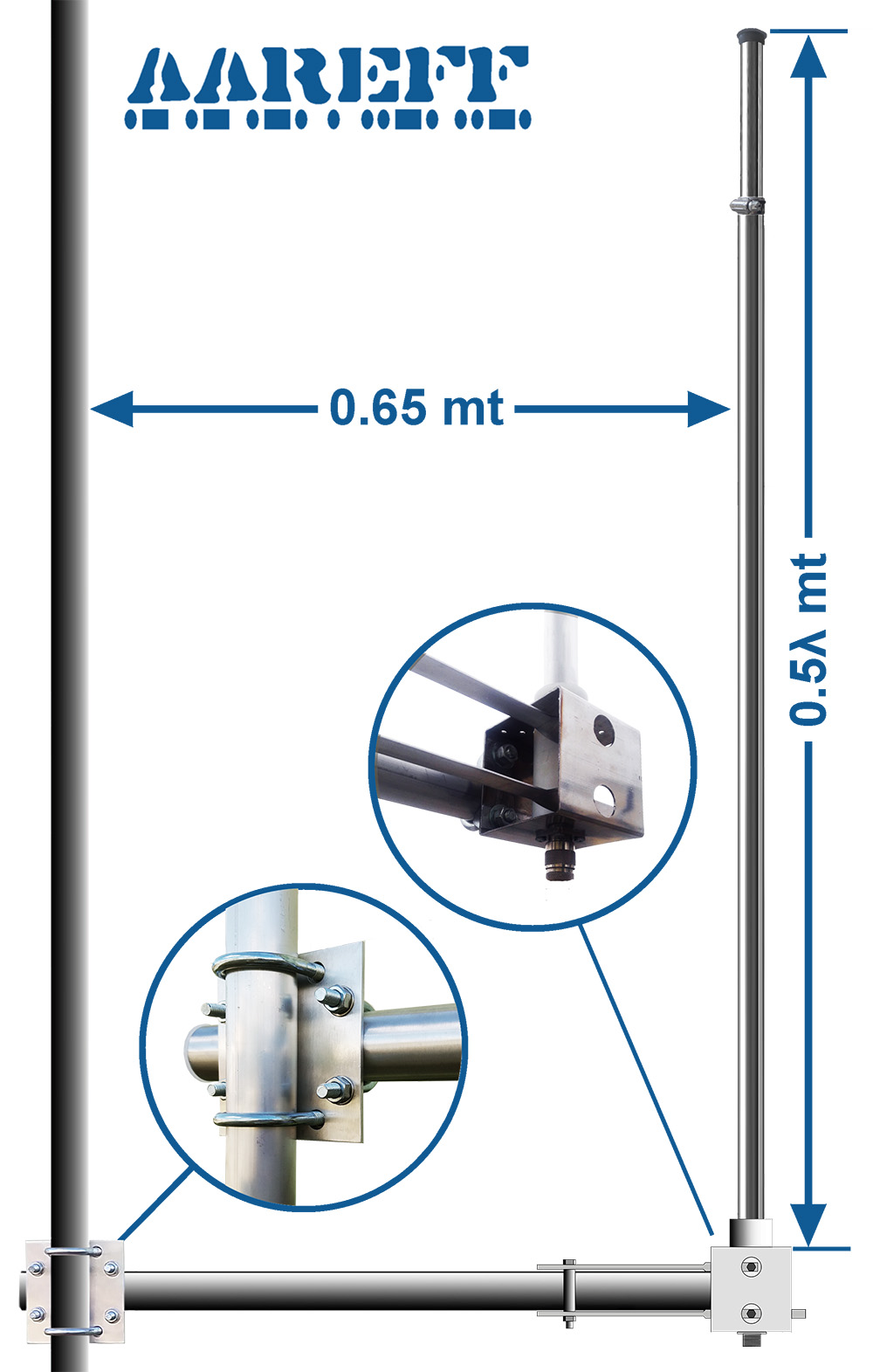
ANTENNA TO MAST / TOWER INSTALLATION
If it all possible you should try and assemble the whole four way half wave antenna system horizontally on the ground to a long 38mm diameter tube. This is much easier and safer. Then when it's all complete, hoist the complete 38mm tube with all the antennas and booms fastened to it, up to the tower. Then clamp by whatever means you have (depends on the tower construction) the whole 38mm tube and antenna assembly vertical to the tower.
1. Mount the 4 half wave antennas and booms to the mast using C the boom to mast / tower mounting clamp assemblies. It is IMPORTANT for correct operation that the dimensions on the diagram are followed as closely as possible, all antennas must be directly above each other in order for the system to work properly and give maximum gain to the horizon.
2. Mount one of the splitter boxes to the tower or mast between the top and second down from top half wave antenna. Mount the other splitter box between the bottom and second up from the bottom half wave antenna.
3. Using the four combo cables of LMR400, blue plugs on one end and green plugs on the other ends, connect the green ends to the outer sockets of the splitter boxes. Then connect the blue ends to each of the four half wave antennas. IMPORTANT! DO NOT CUT BACK, ADD OR CHANGE ANY OF THE COMBO CABLE LENGTHS. To get maximum radiation to the horizon it is important that the signal from each amplifier to each antenna arrives at exactly the same time, this can only happen if the cables are exactly the same length.
4. Connect the two long phased LMR400 antenna cables to the centre sockets of each of the two splitter boxes. Again, IMPORTANT! DO NOT CUT BACK, ADD OR CHANGE THE LONG ANTENNA CABLE LENGTHS. To get maximum radiation to the horizon it is important that the signal from each amplifier to each antenna arrives at exactly the same time, this can only happen if the cables are exactly the same length.
5. MAKE SURE THE CONNECTORS ARE SCREWED PROPERLY AND TIGHT. Wrap PVC or self amalgamating tape tightly around and all over the connectors to make them water resistant.
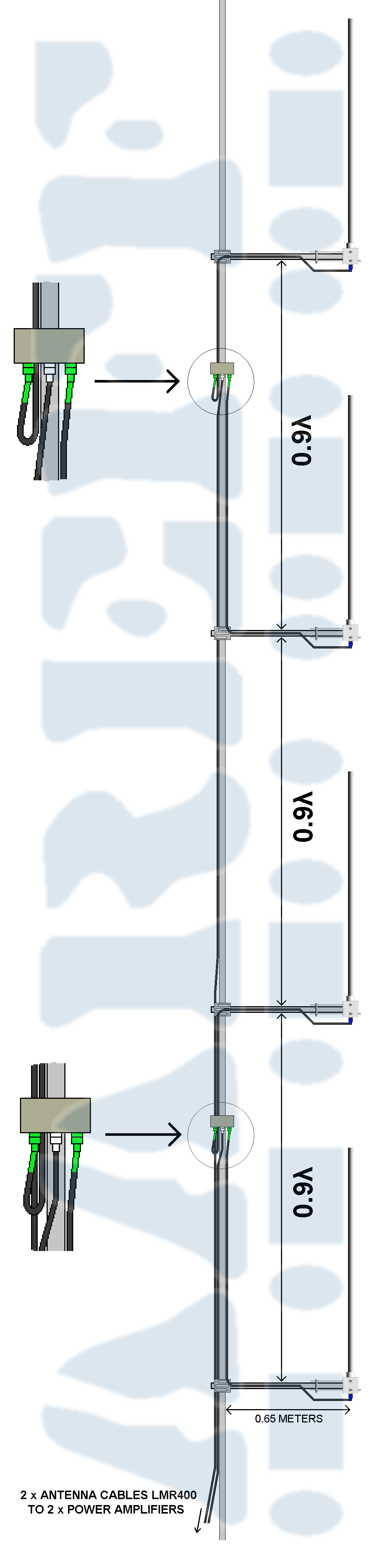
6. Securely fix the 2 cables using PVC tape or large cable ties to the mast as shown in the diagram. Make sure the cables are not going to flap around in the wind. Once again, do not cut back any excess cable. To make the cabling look tidy, it is okay to coil the cable.
7. Make sure that all fixings, brackets and clamps are tight and are not going to work loose over time with wind.
8. On completion of the antenna installation you should have two long LMR400 cables coming down from the antenna assembly ready to plug into each of the large RF power amplifiers.
IMPORTANT!
FOR THIS SYSTEM TO WORK CORRECTLY AND GIVE 8KW ERIP PLUS TO THE HORIZON IT IS VERY IMPORTANT THAT:
1. THE ANTENNAS ARE MOUNTED STRAIGHT VERTICAL AS SHOWN IN THE DIAGRAM
2. THE ANTENNAS ALL LINE UP WITH EACH OTHER
3. THE LENGTHS OF THE LONG ANTENNA CABLES SHOULD NOT BE CHANGED IN ANY WAY
If you need to extend or change the antenna cables, please refer to the section near the end of this document "MODIFYING ANTENNA CABLE LENGTHS"
TRANSMITTER FREQUENCY
When this system was ordered, if a specific frequency was given during the order process, then the system will have been set and factory tested at this frequency. If not, or you need to change the frequency or power level please refer to the user manual for 1W PLL FM STEREO DRIVER / EXCITER WITH AUDIO PROCESSING at aareff.com/1wpllsl19
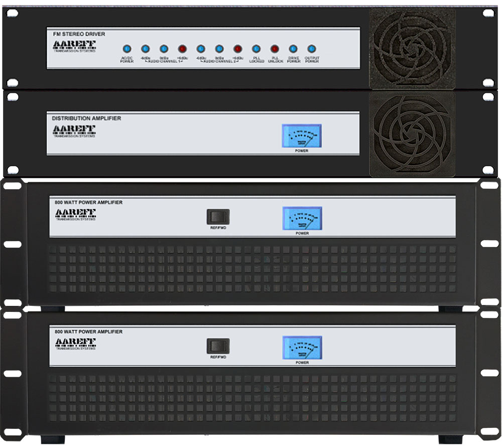
1. Use the supplied M6 screws, nuts, washers and rack rail bars to clamp the Distribution Amplifier (4WDA19), the Driver (1WPLLB and ALSCB) and the two 800W power amplifiers together as shown in the picture. The power amplifiers are much heavier, so these should be at the bottom. The Driver and Distribution Amplifier are light and will suspend in the air and do not need any support at the back.
Alternatively you can mount the units in a professional 19 inch enclosure and integrate the units with other equipment that you have.
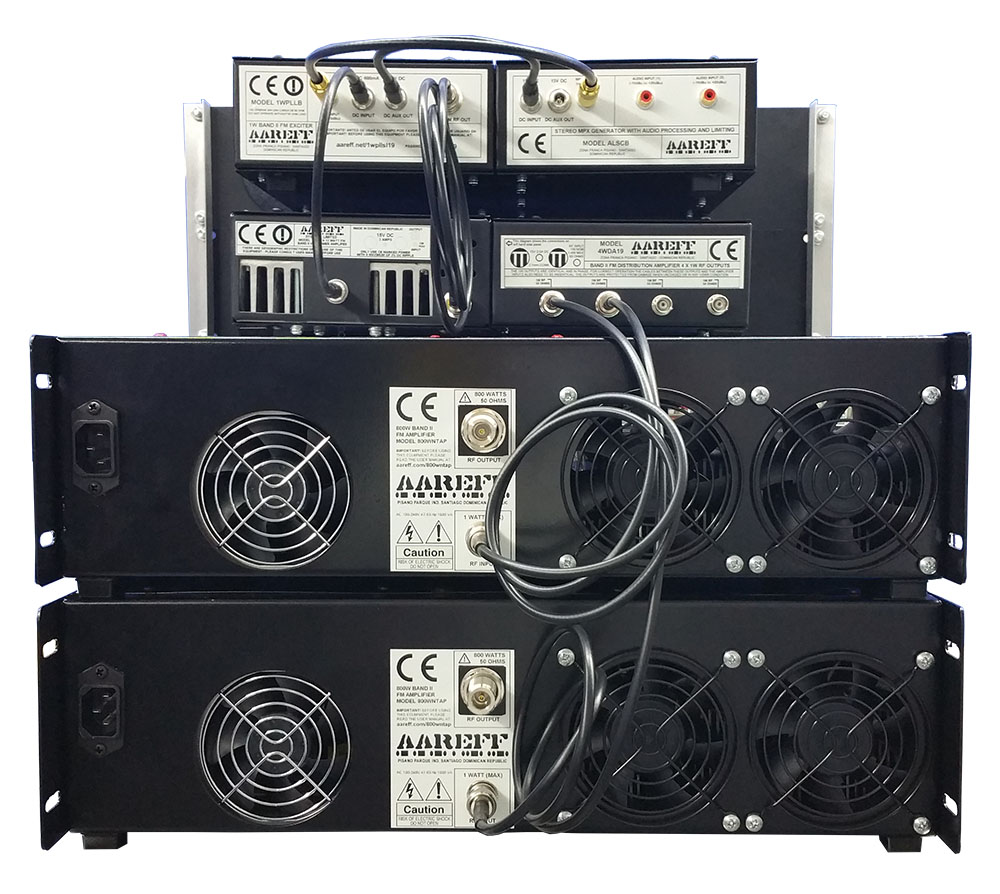
2. Connect the 800 WATTS RF OUTPUT from each power amplifier to the two long LMR400 cables coming down from the antenna assembly. If you find that the cables are longer than necessary, DO NOT shorten these leads as they are a specific phased length. It's okay to coil and cable restrain them to make the arrangement tidier.
3. Using two of the three 1m BNC to BNC leads supplied connect the 1 WATT RF INPUT from each power amplifiers to two of 1W outputs on the Distribution Amplifier (4WDA19). The remaining two spare 1W output on the Distribution Amplifier are left unconnected. You will find that the supplied leads are longer than necessary, DO NOT shorten these leads as they are a specific phased length. It is okay to coil and cable restrain them to make the arrangement tidier.
4. Use the remaining 1m BNC to BNC lead supplied to connect the 1 WATT RF OUTPUT from the 1WPLLB driver / exciter to the Distribution Amplifier 4WDA19 unmarked 1 watt input as shown in the picture.
5. Plug the small 15V DC power supply adapter into the ALSCB DC INPUT. Connect the ALSCB DC AUX OUT to the 1WPLLB DC IN using the short black DC to DC Lead. Connect the 1WPLL DC AUX OUT to the Distribution Amplifier 4WDA19 using the short black DC to DC Lead. Then connect the AC mains power to 15V power supply adapter.
6. Connect mains AC power to the two Power Amplifiers. The driver will lock after a few seconds and Power Amplifiers should indicate power on the front panel meters. The switch on the front panel of the Power Amplifiers should be set to ‘FWD’.
7. Finally, provide an audio input to the ALSCB Stereo Generator and Limiters and you are "ON AIR".
IMPORTANT!
ALWAYS KEEP THE VENTS AND FANS CLEAR
SYSTEM SPECIFICATIONS
| Power Supply | 90-260 VAC 50/60 Hz |
| Transmitter RF Power Output | 2 x 800 Watts (1600 Watts Total) +/- 0.5 dB from -20 to +40 Deg C |
| Freq Stability | Better than +/- 2 KHz from -20 to +40 Deg C +/- 300 Hz typ. |
| Freq Range | 100 KHz steps from 87.5 to 108 MHz |
| Deviation Sensitivity Stability | +/- 2 % max |
| Spurious Emissions | Better than -75dB ref to carrier |
| Harmonic Emissions | Better than -70dB ref to carrier |
| RF Bandwidth | 200 KHz (+/-100 KHz @ -40 dB rtc) |
| Output Connectors | N type 50 ohm |
| RF Ruggedness | Any VSWR any phase any length of time |
| Audio Input Sensitivity | 0 dBu 775 mV rms adjustable |
| Audio Inputs Connector | Phono/ RCA socket |
| Audio S/N Ratio | Better than 70 dB |
| Audio Freq Response | 30 Hz to 15 KHz +/- 0.5 dB |
| Audio Distortion | Better than 0.1 % at +/-75 KHz dev |
| Stereo Crosstalk | 35 dB |
| Pre-emphasis | 50 uS (75 uS USA) or None |
| Pilot Tone Freq | 19 KHz |
| Pilot Tone Stability | 0.2 Hz |
| Antenna Polarisation | Vertical |
| Antenna Gain | (0.9λ Spacing) 6.6 dB + (Isotropic Gain) 2.1 dBi = 8.7 dBi |
| Antenna Cable Loss | -1.2 dB 30m LMR400 foam cable |
| Antenna RF Power Output | 8997 Watts EIRP +/- 0.5 dB (total system gain +7.5 dBi) from -20 to +40 Deg C using 30m of LMR400 foam antenna cable and the four half wave antennas supplied spaced at 0.9λ. |
EQUIPMENT COMPLIANCE (DECLARATION OF CONFORMITY)
European Union
We hereby declare that this equipment complies with;
• ETS 300384 European Telecommunications Harmonised Standard when used with an audio compressor limiter supplied and tested by Aareff
• EN 301489-11 V1.3.1 (2006-05) EMC Electromagnetic Compatibility when used with 1 meter AC mains cord supplied. If the installation engineer needs to extend this cord, this and the audio input cable should be no more than 3 meters in length to remain in compliance with EMC directive.
• 2006/95/EC Directive (2006-12) LVD Low Voltage Directive.
Equipment compliance is possible using equipment from and in conjunction from other manufacturers, but since this is beyond the control of Aareff Systems, Aareff Systems cannot or be expected to guarantee compliance in this situation.
United States
This equipment has not been independently tested by an FCC recognised listed laboratory and for this reason the whole system is not certified. The following list are the technical requirements for the certification of this transmitter. We confirm that this transmitter complies with the technical requirements.
47 CFR Chapter I Federal Communications Commission sections:
• 73.1560, 2.1046 RF Power
• 73.1545, 2.1055 Frequency Stability
• 73.317, 2.1049 (e)(3) Emission Limitation, Emission Mask
• 73.317, 2.1057, 2.1051 Emission Limits, Spurious Emissions at Antenna Terminal
• 73.317, 2.1057, 2.1053 Emission Limits, Field Strength of Spurious Emissions
MODIFYING ANTENNA CABLE LENGTHS
 This is when the lengths of the antenna cables from each of the power amplifier RF outputs to the antenna junction boxes are different lengths.
In this situation signals will arrive at the dipoles at different phases and this will cause a cancellation effect to the combined signal. In worst case the signal gain to the horizon could disappear completely. In best case some of the signal will be radiated, but it will be very poor and inefficient.
 This system is supplied with two identical antenna cable lengths that are phased matched perfectly. If for some reason you need to extend these cables, this can be done, but in the end result they must still be exactly the same length for the antennas to work correctly.
It is important that both signals from the two amplifiers arrive in phase. This can only happen if the total lengths of each of the cables from the power amp connectors to the dipole junction boxes are exactly the same length.
It does not matter how long the cables are, how many cables you use or how many couplers are used to connect the cables together, all that matters is that the total lengths are exactly the same. In practice we have found that a difference or tolerance of up to 2 cm between each cables is acceptable, but no more than this or the signal will not give maximum gain to the horizon.
ROHS
All components used in this apparatus are RoHS compliant and do not contain above the specified limits in any of the following restricted substances:
• Lead
• Hexavalent Chromium
• Mercury
• Cadmium
• Polybrominated Biphenyls (PBB's)
• Polybrominated Diphenylethers (PBDE's)
PRODUCT END OF LIFE
This apparatus must NOT be disposed of with other domestic waste.
We are fully committed to maintaining our responsibilities to the environment. Owners of apparatus that has reached the end of it's useful life can return it to us for recycling, recondition, reuse or proper disposal. You will be required to pay lowest cost postal service available to ship the apparatus to us. Before shipping please contact us for more important information.
LEGAL ADVICE
It is the customer's responsibility to check relevant laws, directives, regulations and licensing requirements before putting this product into service with an antenna system. You, the customer agree to defend, indemnify and hold harmless Aareff Systems Limited, it's employees and agents, from and against any claims, actions or demands, including without limitation legal and accounting fees, alleging or resulting from improper or unlawful use of this product.
© 2017 AAREFF SYSTEMS LIMITED
ALL RIGHTS RESERVED. Aareff is a trademark of Aareff Transmission Systems. All contents of this document including, but not limited to the images, logos, text, illustrations are protected by copyrights, trademarks and other intellectual property rights which are owned and controlled by Aareff Transmission Systems or by other parties that have licensed their material to Aareff Transmission Systems. This document in part or whole may not be copied, reproduced, republished, uploaded, posted or distributed in any way, including by e-mail, ftp or any other electronic means
Every care has been taken in the preparation of this document, errors in content, typographical or otherwise, may have occurred. If you have comments concerning its accuracy, please contact Aareff Systems Limited (UK)


