 +1 829 698 0733
What Do You Need? Talk To Us
+1 829 698 0733
What Do You Need? Talk To Us8am-4pm EST/NY Monday-Friday info@aareff.com

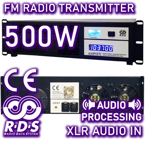
500W FM Transmitter Stereo DDS with RDS and Audio Processing | AAREFF
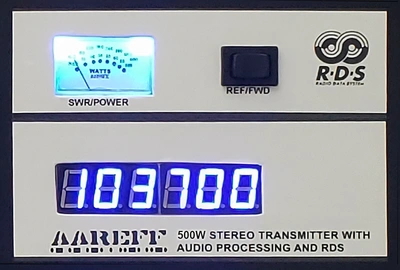
- STEREO WITH AUDIO PROCESSING
- DYNAMIC USB/PC CONTROLLED RDS
- DDS FREQUENCY CONTROL
- ROBUST LDMOS RF OUTPUT
- XLR BALANCED INPUT
- INCLUDES SHIPPING + 5 YEAR WARRANTY
- EXCEEDS CE/FCC TECHNICAL SPECIFICATION

|
LIMITED WARRANTY |
Aareff 500W: Engineered for Regional Dominance & Cost-Efficiency
The Aareff 500W Professional FM Transmitter is the definitive Station-in-a-Box solution for regional broadcasters. Engineered to deliver near-1kW performance with significantly lower power consumption, it offers maximum coverage and regional dominance while slashing operational electricity costs—a critical advantage for stations in high-energy markets.
📻 Pristine Audio Engineering
Features true transformer-balanced XLR inputs to eliminate ground loops and electromagnetic hum, ensuring a noise-free signal for professional 24/7 broadcasting.
Features true transformer-balanced XLR inputs to eliminate ground loops and electromagnetic hum, ensuring a noise-free signal for professional 24/7 broadcasting.
🌍 Regional Powerhouse
The premier choice for commercial hubs in Nigeria, Ghana, and Kenya, and the backbone for national secondary networks in Jamaica and the Bahamas.
The premier choice for commercial hubs in Nigeria, Ghana, and Kenya, and the backbone for national secondary networks in Jamaica and the Bahamas.
Designed for ultimate flexibility, the RF output is fully adjustable from 500 Watts down to zero, allowing you to hit precise EIRP targets and licensing requirements with ease. Whether deployed as a standalone high-power transmitter for an entire region or as a rock-solid exciter for larger arrays, this unit delivers the industrial durability and reliability that modern broadcasters demand.

RF Specification
All stated measurements were made at 220VAC at 27 Deg. Celsius ambient temperature unless stated.
| Power Output | Adj. 1-500 Watts into 50 ohms |
| Spurious Emissions | Less than -75 dB ref to carrier |
| Harmonic Emissions | Less than -70 dB ref to carrier |
| Freq Stability | +/- 1 KHz max. typ. +/-300 Hz |
| Deviation Sensitivity Stability | +/-2 % max |
| Freq Fine Adj | > +/- 1000 Hz |
| Freq Range | 87.5 to 108 MHz in 100 KHz steps |
| Out of Lock RF Muting | Less than -70 dB ref to carrier |
| Residual AM | Less than 0.5 % |
| Synchronous AM | Less than 0.5 % |
| RF Ruggedness | Any VSWR phase or length of time |
| Output Connector | DIN 7-16 |
| Operating Temp | -20 to +40 Deg C |
AF Specification
| Pre-emphasis | (50 uS/ 75 uS/ None) Selectable | |
| Audio Input Connector | XLR True Balanced 600 ohm No Ground Ref./ Floating | |
| Audio Input Sensitivity | +4 dBu for +/- 75 KHz dev. | |
| Version | MPX | Stereo and Audio Processor |
| Signal To Noise Ratio | 80dB | 65dB |
| Frequency Response | 30Hz-76KHz | 30Hz-15KHz |
| Audio Distortion | Better than 0.1% / 60dB THD | Better than 0.1% / 60dB THD |
AC Specification
| Input Voltage | 90-264 V AC 135-370 V DC 47-63 Hz |
| Input Power | 850W for 500W RF OUT with RF SWR less than 1.5 |
| Working Humidity | 20-90% RH non-condensing |
| Safety Standards | UL60950-1 TUV EN60950-1 BSMI CNS14336 CCC GB4943 J60950-1 approved |
| EMC Emission | Compliance to EN55022 class B EN61000-3-2 3 FCC PART 15 / CISPR22 class B CNS13438 class B GB17625.1 |
| EMC Immunity | Compliance to EN61000-4-2 3 4 5 6 8 11 light industry level criteria A |
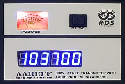
Stereo, RDS, and Advanced Audio Processing FM Transmitter Version
The Ideal Transmitter: Loud, Legal, and Hassle-Free
For Beginners: Features automatic audio level adjustment to ensure your 500 watt transmitter always complies with state regulatory specifications. Effortless setup guaranteed.
For Professionals: Skip manual adjustments. This unit is housed in a single, integrated enclosure, providing everything needed for optimal performance without external clutter.
Smart Audio Processing & Regulatory Compliance
The built-in audio processing is engineered for maximum competitive advantage:
• It achieves a loud, impactful audio level while strictly preventing over-deviation and potential regulatory issues.
• The internal audio processors and stereo functionality are expertly calibrated to maintain the crucial balance between maximum loudness and legal compliance.
-500.webp)
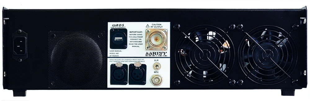
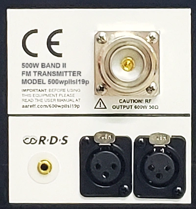
The audio inputs conform to the industry standard: 600 ohm +4 dBu balanced, using XLR connectors.
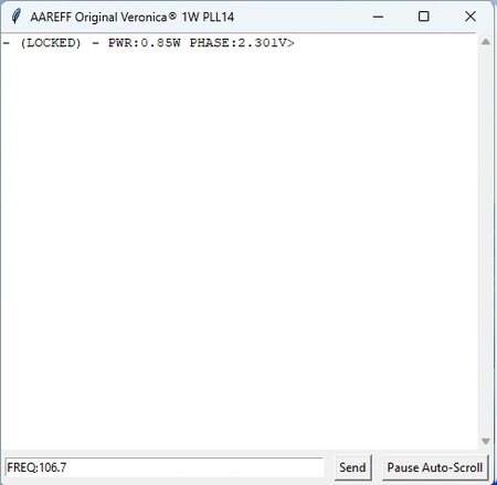
Additionally, this version INCLUDES RDS, allowing your station name and other information to scroll across car radio displays.
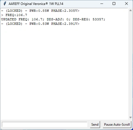
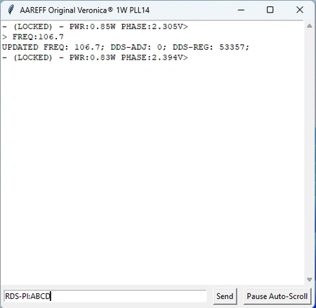
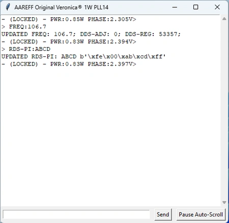
This is not just ordinary RDS; it features fully programmable dynamic RDS. By connecting the transmitter to a PC via USB, you can modify the RDS data in real-time using the USB PC CONTROL shown below.
Flat 30Hz to 76KHz MPX Input Version: Precision for High-End Audio Processors
Professional-Grade Raw MPX Input
This version is specifically available for experienced users who require a straight, raw MPX input for external signal processing.
1. Zero Tilt for Multiband Processors
• The absolute requirement for professional processing is a flat low-frequency response. As proven by our 160Hz Square Wave Test, our input delivers a perfectly square wave with zero tilting. This allows your external processor to maintain absolute control over the modulation, ensuring maximum loudness and a legal signal without low-end artifacts.
-500.webp)
2. Ultra-Stable Hartley VCO & Slow-PLL Architecture
Superior performance starts with a stable foundation. Our Hartley-based, lightly coupled push-pull VCO is so stable it stays within 10kHz of its frequency even with the PLL turned off. This inherent stability leads to two critical performance benefits:
• Ultra-Low Noise: Because the VCO is naturally stable, the PLL only needs to make microscopic corrections (less than 300Hz), resulting in an exceptionally clean and transparent noise floor.
• Preserved Low-End: By heavily low-pass filtering the PLL control voltage to just a few Hz, we ensure 30Hz bass notes pass through the varicap completely unaltered. This preserves the essential low-frequency response demanded by high-performance audio processors.
Result: This preserves the essential low-end audio response demanded by high-performance audio processors.
Antenna Compatibility and EIRP
Recommended FM Broadcast Antennas & EIRP Calculations
The Aareff 500W FM Transmitter is fully compatible with any professional 50 Ohm FM antenna rated for 500 Watts (W) continuous power or higher. Selecting the correct antenna is crucial for maximizing your coverage area and achieving legal Effective Radiated Power (EIRP) limits.
Maximize Your Coverage: Effective Radiated Power (EIRP)
When paired with this powerful 500W transmitter, the following high-gain antennas will generate the corresponding Approximate EIRP.
• Vertical 5/8 Wave FM Antenna: Up to 1.2kW EIRP
• Circular Dipole Antenna: Up to 2.5kW EIRP
• Folded Dipole Antenna: Up to 5kW EIRP
Advanced Transmitter Thermal Management & Protection
Uninterrupted Performance: Intelligent 500W Temperature Control
Our 500-watt transmitters feature a Variable and Linear Temperature Protection system, engineered for maximum uptime and reliability. Unlike conventional designs that abruptly shut down, our technology ensures continuous operation by intelligently managing thermal load.
• Intelligent Power Back-Off: When high temperatures are detected, the transmitter's power output gently reduces (backs off) to prevent the internal heatsink from exceeding the critical threshold of 70C. This linear reduction ensures broadcast stability without sudden interruptions.
Designed for Extreme Reliability
This protective measure is designed to activate only under extreme conditions, reinforcing the system's inherent durability:
• High Ambient Temperature: The ambient operating temperature exceeds 40C
• Impeded Airflow: Fans or ventilation vents are blocked or obstructed.
• Internal Fan Failure: Internal cooling fans fail (typically due to age or lack of maintenance).
Pro Tip for Longevity: Internal fan failure is highly unlikely unless the cooling system is very old and has been severely neglected (e.g., never cleaned). Regular maintenance is key to maximizing your transmitter's lifespan.
SWR Protection: Extreme RF Load Mismatch Resilience
Extremely Rugged Design: The BLF184XR Advantage
Our 500-watt transmitter output is built with bulletproof reliability using the cutting-edge LDMOS BLF184XR power transistor. This component's XR designation stands for 'eXtremely Rugged,' a claim consistently validated by our real-world engineering experience.
• Core Technology: LDMOS RF power transistors are specifically engineered to thrive in the most challenging RF environments and withstand severe load mismatches.
• Expert Integration: This superior transistor technology is combined with our advanced VSWR reflected power protection circuits to maintain transmitter uptime even in the most extreme circumstances.
Intelligent, Gentle Power Management
Mirroring our intelligent thermal control, the VSWR protection system is designed for continuity, not interruption:
• Linear Power Back-Off: When a high VSWR condition is detected, the protection circuit gently and linearly reduces the power output to a safe operating level.
• Zero Abrupt Shutdowns: This prevents an abrupt cut-off or total shutdown, ensuring your broadcast signal remains as continuous as possible while the mismatch issue is resolved.
Robust Transmitter Construction & Enclosure Design
The 500 watt transmitter is housed in a 3U enclosure. This is fabricated in strong 16-gauge steel, powder coated and baked in black. There are no flimsy metal panels like you find on Chinese transmitters, our enclosures are super strong and suitable for military use. The black powder coating protects the enclosure from superficial damage which in turn prevents corrosion and rust from developing extended the long-term life of the transmitter significantly.
Professional-Grade Durability and Materials
Our 500-Watt FM Transmitter is housed within a professional-grade 3U Rackmount Enclosure, engineered for maximum resilience and longevity in demanding environments. We prioritize superior construction over cost-cutting measures:
• Heavy-Duty Steel: The chassis is fabricated from strong 16-gauge steel, providing exceptional structural integrity and protection for internal components.
• Corrosion Protection: The steel is finished with a high-quality black powder coating that is baked on, creating a durable, protective shell.
Long-Term Reliability and Military Suitability
This robust construction delivers significant long-term benefits and reinforces our commitment to quality:
• 16-Gauge Steel: Eliminates flimsy metal panels common in low-quality units, ensuring a super strong chassis.
• Powder Coating: Protects the enclosure from superficial damage, preventing corrosion and rust development.
• Military Use Suitability: The super-strong enclosures are suitable for military-standard use, significantly extending the transmitter’s overall service life.
Precision Control: Frequency, Power, and Deviation
Adjusting frequency and power levels is straightforward yet secure. To prevent accidental or unauthorized changes, we have engineered a hardware-based compromise by placing essential controls on the underside of the chassis. By simply sliding the unit out of the rack and inverting it, you gain direct access to the DIP switches and trim pots for precise calibration.
This professional design ensures that critical broadcast parameters—including frequency, power output, and FM deviation—remain exactly where you set them. This manual configuration method offers a layer of physical security that software-only buttons cannot match, protecting your station from inadvertent interference or regulatory violations.
Compliance
The stereo version with audio processing and limiting meets all the regulatory standards required out of the box and pre configured. In fact if you send us a copy of your permit and it's conditions, we will set it up exactly to the specification. This equipment complies with EU/CE harmonised standards and FCC technical requirements for FM broadcasting. More information HERE
Do You Have A Question?
Web Based Audio, Control and Monitoring (OPTION)
Stay connected to your transmitter anywhere, anytime. With AAREFF’s web based remote control and monitoring option, you can monitor and manage critical performance data in real time without needing to travel to site.
- Web Interface & Secure Login – access your transmitter from any browser
- Real-Time Monitoring – forward/reflected power, VSWR, temperature, and supply voltage
- Remote Control Functions – switch RF on/off, adjust power levels, change and fine tune the frequency
- Flexible Connectivity – connect easily via LAN, VPN, or our secure web interface — designed to work even behind firewalls.
This feature not only gives engineers the tools they need, but also provides peace of mind for station managers by reducing downtime, lowering maintenance costs, and ensuring your broadcast runs smoothly 24/7.
THE INTERFACE SHOWN BELOW IS A REAL LIVE!! TRANSMITTER, ONLINE NOW, IN OUR WORKSHOP
> PRESS < the RED speaker icon, wait 4 secs and you will hear the real-time sound being fed to the transmitters audio input section. It will work on mobile, but it looks better on desktop as its designed to be on view in the studio computer.
What You See in the Remote Dashboard
The AAREFF remote control interface provides engineers with a complete overview of transmitter and system status in real time:
- Connection & Device Info – online/offline status, LAN & external IP, device ID
- System Performance – CPU load, processor type, disk usage, memory load, lock status
- Operating Conditions – internal temperature, supply voltages, calibration states
- Transmitter Parameters – frequency, forward power, VSWR, phase voltage, DDS/PLL control
- Real-Time Alarms – instant alerts when parameters go out of range
From anywhere in the world, you can securely monitor, troubleshoot, and control your AAREFF / Veronica FM transmitter, ensuring maximum uptime and peace of mind.
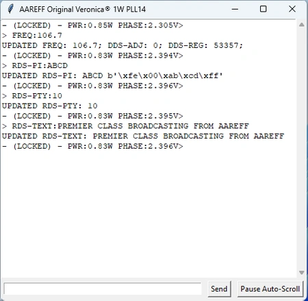
Internal Microprocessor Logging
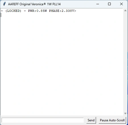
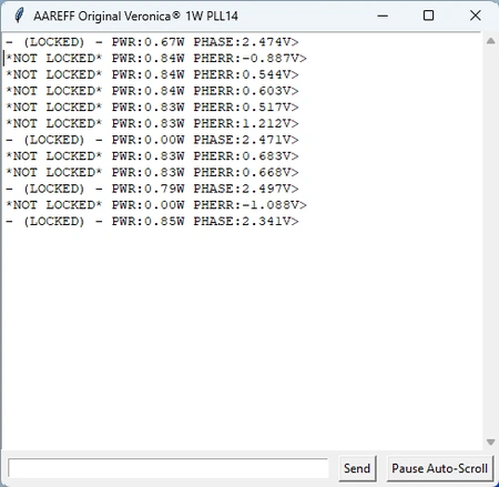
Every AAREFF / Veronica transmitter is supervised by an embedded microprocessor that continuously records system activity. The internal log provides engineers with precise, time-stamped updates of operating conditions and broadcast data.
- Time-Stamped Events – detailed logs of all changes and updates
- Operating State – PLL lock status, frequency, RF power output
- Live Parameters – phase voltage, VCO levels, calibration values, DDS registers
- Device Information – unique transmitter ID and system identifiers
- Configuration Updates – records frequency adjustments and parameter changes
- RDS Activity – logs text messages, program IDs (PI), PTY codes, and 57kHz carrier status
- Diagnostic Data – low-level register outputs for troubleshooting
This level of transparency ensures engineers can track performance, confirm settings, and diagnose issues quickly whether on site or connected remotely.
Web-Based Control Panel
The AAREFF remote interface allows engineers to configure transmitter and RDS settings directly from any browser, providing complete flexibility and instant control.
- Frequency & Power – set operating frequency and adjust RF output remotely
- DDS Calibration – fine-tune digital synthesis for precise operation
- RDS Text – edit scrolling station messages in real time
- Program Identification – configure PI codes and PTY types
- RDS Carrier Control – switch the 57 kHz subcarrier on or off instantly
- Service Commands – enter advanced commands for maintenance
With this secure, web-based control panel, you can manage your transmitter and RDS data from anywhere in the world.


 The ANTENNA is very important, check this is installed and ready to use. DO NOT EVER POWER A TRANSMITTER OR RF AMPLIFER WITHOUT AN ANTENNA CONNECTED.

 Do not adjust any factory set internal controls.