 +1 829 698 0733
What Do You Need? Talk To Us
+1 829 698 0733
What Do You Need? Talk To Us8am-4pm EST/NY Monday-Friday info@aareff.com

User Manual and Installation of Two Stacked Half Wave Vertical Antenna
ANTENNA PACKAGE CHECKLIST
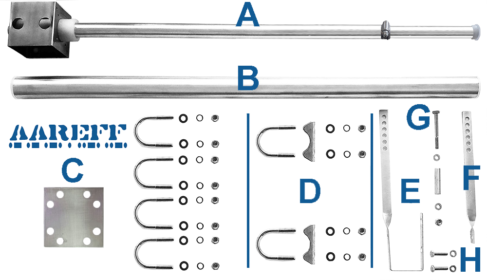
| Qty | Set | Description |
| 2 | A | 1/2 wave, base, 25mm dia. main radiator, 22mm dia. top adjust tube and tube clamp |
| 2 | B | 38mm x 800mm boom tube |
| 2 | C | Boom to mast/ tower mounting clamp. Each set includes, 1 x 100mm square 3.2mm thick clamping plate, 4 x 38mm U bolts with M8 threads, 8 x M8 spring washers, 8 x M8 plain washers and 8 x M8 nuts |
| 2 | D | Antenna base to boom U bolts clamp assemblies. Each set includes 2 x 38mm U bolts with M8 threads, 2 x 38mm tube clamp, 4 x M8 spring washers, 4 x M8 plain washers and 4 x M8 nuts |
| 2 | E | Bottom tuning bar |
| 2 | F | Top tuning bar |
| 2 | G | Tuning bar M6 screw, 1 aluminium sleeve, 2 M6 washers and 1 M6 nut |
| 2 | H | Tuning bar M6 screws and washers |
| Qty | Description | Item |
| 1 | Splitter Boxes | 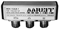 |
| 2 | Combo cable LMR400 (2.93 mt BLUE plug) and RG11 (0.63 mt) GREEN plug, total length 3.56 mt |  |
 IMPORTANT! INSTALLATION NEAR TO POWER LINES
- Erect antenna on pole, mast or tower as far away as possible from the power lines
- Avoid crossing antenna cables under electrical power lines
- Do not attach antennas to towers, poles or similar structures carrying electrical power lines
- If you are not experienced in installation of antennas, have experienced persons assist you
- During installation, tie off antenna with a rope so if it falls it can be diverted away from the power lines
- Avoid fastening antennas, especially self-supporting types, to old chimneys or to any chimney not designed to take such stress. Forces created by a strong wind may be sufficient to topple both chimney and antenna
ELECTROMAGNETIC COMPATIBILITY
When writing this manual there was no EU directive regarding the EMC compatibility of Band II VHF broadcast antennas, however in our view there are some potential EMC compatibility issues that need to be addressed when installing this antenna system. On completion of the antenna installation check;
- All the cables entering the connectors are tight and properly crimped or soldered
- All the connectors are screwed in tight and sound
- PVC insulation tape and/or self amalgamating tape are wrapped around all the connectors to stop water entering the connector and the inside of the body of the cable
- If any cables are loose or there are bad connections this can cause some non-linear resistance, diode action or some small arcing. When this happens it creates EMC disturbance (arcing and crackling sound) across a wide frequency spectrum
TO ERECT THIS ANTENNA YOU WILL NEED TO PROVIDE
- PVC insulation tape and/or self amalgamating tape
- Metric tape measure at least 3m
- Two 13mm spanners, one with a ringed end
- 10mm socket and wrench
- Flat medium size screwdriver
- A secure mounting mast with a diameter of 38mm (1 1/2 inch) and clear length of at least 7 meters for mounting the antennas to.
ASSEMBLING THE TWO HALF WAVE ANTENNA BASE SECTIONS
Using the following items to assemble the four antenna base sections with the tuning loops as shown in the picture below.
1 x (A) 0.5λ (half wave) radiator and base
2 x (D) Antenna base to boom U bolts clamp assemblies
1 x (F) Top tuning bar
1 x (E) Bottom tuning bar
2 x (H) M6 screws and 2 washers
1 x (G) Tuning bar M6 screw, 1 x aluminium sleeve, 2 x M6 washers and 1 x M6 nut
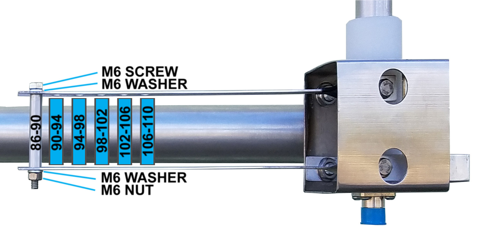
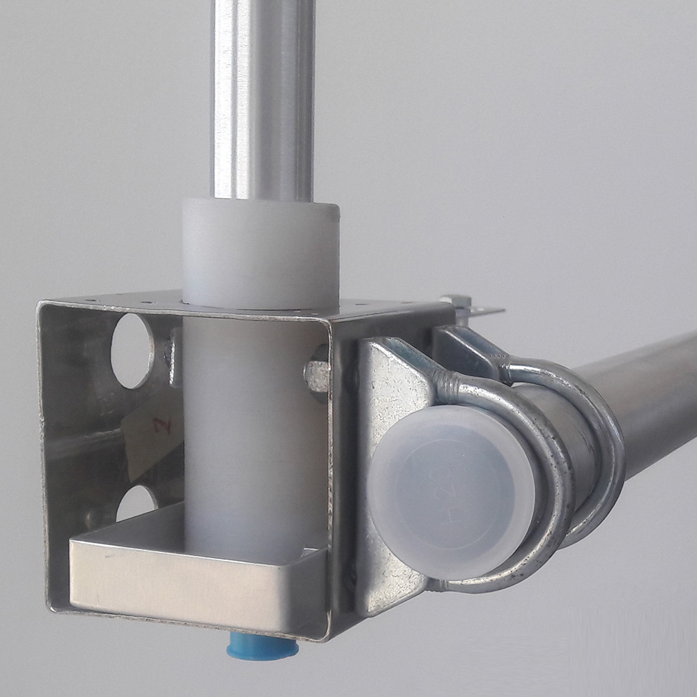
1. The tuning loop, bar and aluminium sleeve form an half turn inductor. The operating frequency determines the position of the aluminium sleeve. Put the aluminium sleeve in one of the six positions shown in picture for the frequency that you want. This sleeve will be carrying a huge RF current, make sure it is tight and firm. The tuning loop and bar should also be screwed tight to the Teflon section with the two M6 screws and washers. This is shown in the pictures.
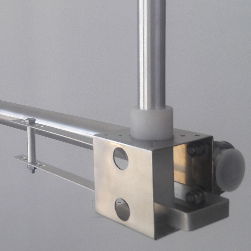
2. The bottom tuning bar should also be clamped tight to the back plate of the base and the 38mm x 800mm boom tube using the U bolt clamp assemblies. Again as shown in the picture below.
ADJUSTING THE SPACING AND THE LENGTH
Pick the frequency (MHz) from the table that is the closest to frequency you need to use. For example if you needed 91.3 MHz, then you would pick 91 MHz, this is the closest.
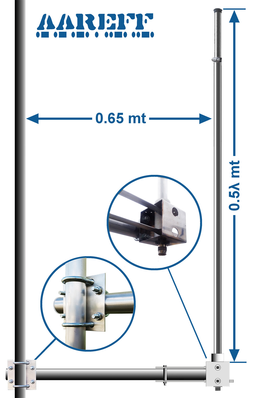
1. Adjust the radiator to length shown in metres for 0.5λ (wavelength). Use a metric tape measure to measure the length from the (IMPORTANT) top plate of the base section to the end of the top tube. Slide the top radiator tube inside the bottom large radiator tube until the correct length is reached. At the correct length tighten the circular screw clip to secure the two tubes in place. Make sure the clip is tight and the tubes don't move. DOUBLE check the length again from the top plate of the base section to the end of the top tube. If this length is not correct, the antenna will not radiate correctly and there'll be high reflected power and SWR.
2. Adjust the distance / spacing between the booms for the frequency of 0.9λ (wavelength). This is not a critical measurement and only needs to be accurate to +/- 2 or 3 cm of the length shown in the table. This spacing optimises the complete antenna system to give maximum gain to the horizon.
| FREQ. MHz | 0.9λ Vertical Spacing | 0.5λ Radiator Length |
| 87 MHz | 3.10 mt | 1.64 mt |
| 88 MHz | 3.07 mt | 1.62 mt |
| 89 MHz | 3.03 mt | 1.60 mt |
| 90 MHz | 3.00 mt | 1.58 mt |
| 91 MHz | 2.97 mt | 1.57 mt |
| 92 MHz | 2.93 mt | 1.55 mt |
| 93 MHz | 2.90 mt | 1.53 mt |
| 94 MHz | 2.87 mt | 1.52 mt |
| 95 MHz | 2.84 mt | 1.50 mt |
| 96 MHz | 2.81 mt | 1.48 mt |
| 97 MHz | 2.78 mt | 1.47 mt |
| FREQ. MHz | 0.9λ Vertical Spacing | 0.5λ Radiator Length |
| 98 MHz | 2.76 mt | 1.45 mt |
| 99 MHz | 2.73 mt | 1.44 mt |
| 100 MHz | 2.70 mt | 1.43 mt |
| 101 MHz | 2.67 mt | 1.41 mt |
| 102 MHz | 2.65 mt | 1.40 mt |
| 103 MHz | 2.62 mt | 1.38 mt |
| 104 MHz | 2.60 mt | 1.37 mt |
| 105 MHz | 2.57 mt | 1.36 mt |
| 106 MHz | 2.55 mt | 1.34 mt |
| 107 MHz | 2.52 mt | 1.33 mt |
| 108 MHz | 2.50 mt | 1.32 mt |
ANTENNA TO MAST / TOWER INSTALLATION
If it all possible you should try and assemble the two way half wave antenna system horizontally on the ground to a long 38mm diameter tube. This is much easier and safer. Then when it's all complete, hoist the complete 38mm tube with all the antennas and booms fastened to it, up to the tower. Then clamp by whatever means you have (depends on the tower construction) the whole 38mm tube and antenna assembly vertical to the tower.
1. Mount the two half wave antennas and booms to the mast using C the boom to mast / tower mounting clamp assemblies. It is IMPORTANT for correct operation that the dimensions on the diagram are followed as closely as possible, both antennas must be directly above each other in order for the system to work properly and give maximum gain to the horizon.
2. Mount the splitter box to the tower or mast between the top and bottom half wave antenna.
3. Using the two combo cables of LMR400, blue plugs on one end and green plugs on the other ends, connect the green ends to the outer sockets of the splitter box. Then connect the blue ends to each of the two half wave antennas. IMPORTANT! DO NOT CUT BACK, ADD OR CHANGE ANY OF THE COMBO CABLE LENGTHS. To get maximum radiation to the horizon it is important that the signal to each antenna arrives at exactly the same time, this can only happen if the cables are exactly the same length.
4. Connect the main feeder cable from the transmitter to the centre socket of the splitter box.
5. MAKE SURE THE CONNECTORS ARE SCREWED PROPERLY AND TIGHT. Wrap PVC or self amalgamating tape tightly around and all over the connectors to make them water resistant.
6. Securely fix the cables using PVC tape or large cable ties to the mast as shown in the diagram. Make sure the cables are not going to flap around in the wind. Once again, do not cut back any excess cable. To make the cabling look tidy, it is okay to coil the cable.
7. Make sure that all fixings, brackets and clamps are tight and are not going to work loose over time with wind.
8. On completion of the antenna installation you should have a long cable coming down from the antenna assembly ready to plug into the transmitter
IMPORTANT!
FOR THIS ANTENNA TO WORK CORRECTLY AND GIVE 5.4 dBi TO THE HORIZON IT IS VERY IMPORTANT THAT:
1. THE ANTENNAS ARE MOUNTED STRAIGHT VERTICAL AS SHOWN IN THE DIAGRAM
2. THE ANTENNAS LINE UP WITH EACH OTHER
TECHNICAL SPECIFICATION
| Antenna Gain (Isotropic) | +5.4 dBi |
| Frequency Range | 87 - 109 MHz |
| Bandwidth | +/-2 MHz for SWR of 1.5 SWR 1.1 Max at tuned frequency |
| Construction | Aluminium and Teflon |
| RF Connectors | N type |
| Impedance | 50 ohm (1.1 SWR) unbalanced input |
| Polarisation | Vertical |
| Maximum RF Power | 1kW |
| Weight of Antenna | 4 Kg |
| Wind Speed Handling | 90 MPH Minimum |
ANY QUESTIONS?
NEED TO BUY ONE?
ROHS
All components used in this apparatus are RoHS compliant and do not contain above the specified limits in any of the following restricted substances:
� Lead
� Hexavalent Chromium
� Mercury
� Cadmium
� Polybrominated Biphenyls (PBB's)
� Polybrominated Diphenylethers (PBDE's)
PRODUCT END OF LIFE
This apparatus must NOT be disposed of with other domestic waste.
We are fully committed to maintaining our responsibilities to the environment. Owners of apparatus that has reached the end of it's useful life can return it to us for recycling, recondition, reuse or proper disposal. You will be required to pay lowest cost postal service available to ship the apparatus to us. Before shipping please contact us for more important information.
LEGAL ADVICE
It is the customer's responsibility to check relevant laws, directives, regulations and licensing requirements before putting this product into service with an antenna system. You, the customer agree to defend, indemnify and hold harmless Aareff Systems Limited, it's employees and agents, from and against any claims, actions or demands, including without limitation legal and accounting fees, alleging or resulting from improper or unlawful use of this product.
� 2019 AAREFF SYSTEMS LIMITED
ALL RIGHTS RESERVED. Aareff is a trademark of Aareff Transmission Systems. All contents of this document including, but not limited to the images, logos, text, illustrations are protected by copyrights, trademarks and other intellectual property rights which are owned and controlled by Aareff Transmission Systems or by other parties that have licensed their material to Aareff Transmission Systems. This document in part or whole may not be copied, reproduced, republished, uploaded, posted or distributed in any way, including by e-mail, ftp or any other electronic means
Every care has been taken in the preparation of this document, errors in content, typographical or otherwise, may have occurred. If you have comments concerning its accuracy, please contact Aareff Systems Limited (UK)


