 +1 829 698 0733
What Do You Need? Talk To Us
+1 829 698 0733
What Do You Need? Talk To Us8am-4pm EST/NY Monday-Friday info@aareff.com

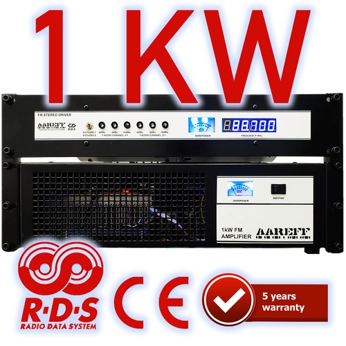
1kW FM Transmitter Stereo DDS with RDS and Audio Processing | AAREFF
- Robust 1kW LDMOS RF Output (Engineered for 24/7 Reliability)
- Built-in Stereo with Advanced Audio Processing
- Dynamic USB/PC Controlled RDS (Radio Data System)
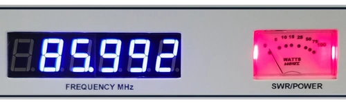
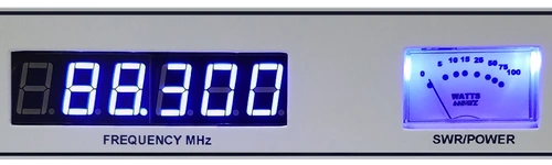
- Rock-Solid DDS Frequency Control (Zero Signal Drift)
- Professional XLR Balanced Audio Inputs for Ultra-Low Noise
- Exceeds CE & FCC Technical Specifications
- Backed by an Industry-Leading 5-Year Warranty
- Includes 100% Free Global Delivery

|
LIMITED WARRANTY |
BUILT BY EXPERTS. GUARANTEED FOR 5 YEARS.
This Aareff 1kW FM Transmitter is engineered for serious broadcasting. It includes every feature necessary for a professional station, from the DDS Exciter and Stereo Audio Processing to the Dynamic USB/PC Controlled RDS. High power combined with the right FM antenna (e.g., an 8-bay stacked dipole) can propel your signal up to 100km, creating a formidable 10kW EIRP system.
Superior Engineering & Compliance
- ✔ Robust LDMOS RF Output: Ensures exceptional durability and handles high power demands with ease.
- ✔ DDS Frequency Control: Rock-solid stability to avoid signal drift and maintain licensed accuracy.
- ✔ CE/FCC Compliance: Meets the highest international broadcasting standards for safety and performance.
- ✔ XLR Balanced Input: Professional-grade input eliminates noise for crystal-clear audio quality.
SIMPLE 3-STEP INSTALLATION
If your objective is achieving massive broadcast distance or penetrating concrete and steel in dense urban centers, this is your solution. You do not need an RF engineering degree to turn it on—all you need is a quality mixer.
- 1. Audio Connection: Connect the output of your mixer directly to the gold-plated RCA inputs on the back of the driver unit.
- 2. Antenna Connection: Connect the 1000W output to your tuned 50-ohm antenna system.
- 3. Power Up: Switch it on. If you see zero reflected power on the front panel, you are successfully broadcasting serious power.
Do You Have A Question?
RF Specification
All stated measurements were made at 220VAC at 27 Deg. Celsius ambient temperature unless stated.
| Power Output | Adj. 1-1000 Watts into 50 ohms |
| Spurious Emissions | Less than -75 dB ref to carrier |
| Harmonic Emissions | Less than -70 dB ref to carrier |
| Freq Stability | +/- 1 KHz max. typ. +/-300 Hz |
| Deviation Sensitivity Stability | +/-2 % max |
| Freq Fine Adj | > +/- 1000 Hz |
| Freq Range | 87.5 to 108 MHz in 100 KHz steps |
| Out of Lock RF Muting | Less than -70 dB ref to carrier |
| Residual AM | Less than 0.5 % |
| Synchronous AM | Less than 0.5 % |
| RF Ruggedness | Any VSWR phase or length of time |
| Output Connector | DIN-716 |
| Operating Temp | -20 to +40 Deg C |
AF Specification
| Pre-emphasis | (50 uS/ 75 uS/ None) Selectable | |
| Audio Input Connector | XLR True Balanced 600 ohm No Ground Ref./ Floating | |
| Audio Input Sensitivity | +4 dBu for +/- 75 KHz dev. | |
| Version | MPX | Stereo and Audio Processor |
| Signal To Noise Ratio | 80dB | 65dB |
| Frequency Response | 30Hz-76KHz | 30Hz-15KHz |
| Audio Distortion | Better than 0.1% / 60dB THD | Better than 0.1% / 60dB THD |
AC Specification
| Input Voltage | 90-264 V AC 135-370 V DC 47-63 Hz |
| Input Power | 1400W for 1000W RF OUT with RF SWR less than 1.5 |
| Working Humidity | 20-90% RH non-condensing |
| Safety Standards | UL60950-1 TUV EN60950-1 BSMI CNS14336 CCC GB4943 J60950-1 approved |
| EMC Emission | Compliance to EN55022 class B EN61000-3-2 3 FCC PART 15 / CISPR22 class B CNS13438 class B GB17625.1 |
| EMC Immunity | Compliance to EN61000-4-2 3 4 5 6 8 11 light industry level criteria A |
Stereo, RDS, and Audio Processing Version: The Ultimate All-in-One FM Broadcast Solution
Optimal Performance & Compliance: Why Choose This Version?
If you're seeking a transmitter that balances powerful broadcasting with strict legal compliance, this version is your definitive choice. It eliminates complexity for both new and experienced broadcasters.
• Beginner-Ready: The unit features automatic audio level adjustment, ensuring your 1000 watt transmitter always adheres to state regulator specifications. Start broadcasting legally and effortlessly.
• Professional-Grade: Ideal for experienced users who prioritize efficiency. It includes everything in one single enclosure, minimizing setup time and cable clutter.
Intelligent Audio Processing for Maximum Reach
Our internal audio processors are engineered to give you a competitive edge:
• The processing keeps the audio level LOUD—allowing your station to compete effectively with others on the dial.
• Crucially, it prevents over deviation, ensuring your powerful signal remains legal and compliant with all permit requirements.
• This version perfectly executes the delicate balance of maximum loudness while maintaining a legal signal.
-500.webp)
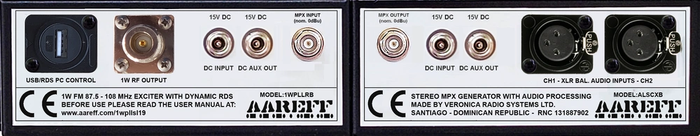
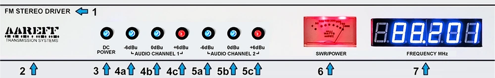
The audio inputs industry standard 600 ohm +4 dBu balanced using XLR connectors.
In addition, this version INCLUDES RDS. This allows everybody to see your station name and more scrolling across the car radio display.
The RDS is not just ordinary RDS, it is fully programmable dynamic RDS. This means the transmitter can be connected to a PC by a USB cable. The RDS can be changed on the fly in real time by using USB PC CONTROL shown below.
Flat 30Hz to 76KHz MPX Input Version: Precision for High-End Audio Processors
Professional-Grade Raw MPX Input
This version is specifically available for experienced users who require a straight, raw MPX input for external signal processing.
1. Zero Tilt for Multiband Processors
• The absolute requirement for professional processing is a flat low-frequency response. As proven by our 160Hz Square Wave Test, our input delivers a perfectly square wave with zero tilting. This allows your external processor to maintain absolute control over the modulation, ensuring maximum loudness and a legal signal without low-end artifacts.
-500.webp)
2. Ultra-Stable Hartley VCO & Slow-PLL Architecture
Superior performance starts with a stable foundation. Our Hartley-based, lightly coupled push-pull VCO is so stable it stays within 10kHz of its frequency even with the PLL turned off. This inherent stability leads to two critical performance benefits:
• Ultra-Low Noise: Because the VCO is naturally stable, the PLL only needs to make microscopic corrections (less than 300Hz), resulting in an exceptionally clean and transparent noise floor.
• Preserved Low-End: By heavily low-pass filtering the PLL control voltage to just a few Hz, we ensure 30Hz bass notes pass through the varicap completely unaltered. This preserves the essential low-frequency response demanded by high-performance audio processors.
Result: This preserves the essential low-end audio response demanded by high-performance audio processors.
Maximize Your Reach: Professional Antennas
This high-performance transmitter will operate flawlessly with any 50 ohm antenna rated for 1000W or higher. However, pairing it with an Aareff high-gain antenna will drastically multiply your Effective Isotropic Radiated Power (EIRP).
- Vertical 5/8 Wave: Ideal for single-bay, long-distance ground wave coverage.
- 4-Way Stacked Dipole: Excellent gain and pattern control.
- 8-Way Stacked Dipole: High-gain solution for maximizing your ERP.
Need a Complete Ready-to-Air Solution?
Skip the guesswork. Our 2.5kW, 5kW, and 10kW EIRP packages include this exact 1kW transmitter packaged with premium coaxial cable and perfectly matched antennas.
VIEW COMPLETE EIRP SYSTEMS
Skip the guesswork. Our 2.5kW, 5kW, and 10kW EIRP packages include this exact 1kW transmitter packaged with premium coaxial cable and perfectly matched antennas.
VIEW COMPLETE EIRP SYSTEMS
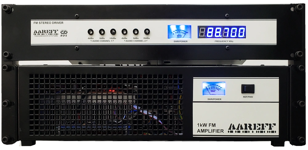
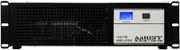
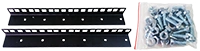
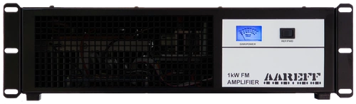
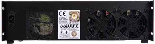
Robust Construction & Enclosure Design
This 1kW system is housed in a robust, dual-enclosure setup (1x 3U, 1x 2U) designed to fit any standard 19-inch rack. Utilizing heavy-duty 16-gauge steel, the metalwork meets high-stress, military-grade requirements. The baked-on satin black powder coating provides a highly scratch-resistant, rust-proof surface.
Fully CE & FCC Compliant
The stereo version with audio processing meets all regulatory standards out of the box. If you send us a copy of your broadcast permit, we will configure the unit exactly to your local specifications before shipping. This equipment strictly complies with EU/CE harmonised standards and FCC technical requirements. View Compliance Details.
Dynamic RDS (Radio Data System) Included
![]()
The stereo version comes complete with fully programmable dynamic RDS. Connect the transmitter to a PC via USB, and the circuit will automatically extract the Artist and Song name from your DJ playout software (like Zara Studio) and broadcast it to car radios. Learn more about RDS setup.
Extreme Temperature Resilience: 24/7 Continuous Performance
Field-Proven Durability: This unit is engineered for the world's most demanding environments. The original design was successfully deployed in East Africa five years ago and remains fully operational 24/7, enduring intense, continuous heat.
Intelligent Protection and Auto-Recovery: Our advanced protection system ensures the longevity of your investment, providing automatic fail-safes without abrupt disruptions.
- Over-Temperature Protection: If internal temps exceed 70°C, the system triggers a gentle RF power back-off (soft reduction) to avoid abrupt cuts. It automatically restores full power when temperatures stabilize.
- Reflected Power Protection: If a high VSWR is detected (indicating an antenna fault), power is safely reduced to prevent damage. It auto-recovers instantly once the fault is cleared.
The Benefit: In the event of extreme heat or antenna damage, the power is safely reduced. Once resolved, the unit restores full power, minimizing station downtime.
VSWR Resilience: The BLF188XR Transistor
The heart of this model's final output stage is the BLF188XR LDMOS RF power transistor. The 'XR' designation stands for 'eXtremely Rugged,' signifying its design for the most demanding engineering environments.
Zero Downtime VSWR Protection:
- Extreme Load Handling: Withstands a severe load mismatch (VSWR greater than 65:1). This ensures unparalleled resilience against real-world antenna failures or lightning strikes.
- Automatic Foldback: Power is automatically and gently reduced to a safe level to prevent any component damage.
- Conservative Operation: While capable of 1600W peak output, we conservatively run it at a maximum of 1kW. This drastically extends the system's longevity and ultra-reliability.
Web Based Audio, Control and Monitoring (OPTION)
Stay connected to your transmitter anywhere, anytime. With AAREFF’s web based remote control and monitoring option, you can monitor and manage critical performance data in real time without needing to travel to site.
- Web Interface & Secure Login – access your transmitter from any browser
- Real-Time Monitoring – forward/reflected power, VSWR, temperature, and supply voltage
- Remote Control Functions – switch RF on/off, adjust power levels, change and fine tune the frequency
- Flexible Connectivity – connect easily via LAN, VPN, or our secure web interface — designed to work even behind firewalls.
This feature not only gives engineers the tools they need, but also provides peace of mind for station managers by reducing downtime, lowering maintenance costs, and ensuring your broadcast runs smoothly 24/7.
THE INTERFACE SHOWN BELOW IS A REAL LIVE!! TRANSMITTER, ONLINE NOW, IN OUR WORKSHOP
> PRESS < the RED speaker icon, wait 4 secs and you will hear the real-time sound being fed to the transmitters audio input section. It will work on mobile, but it looks better on desktop as its designed to be on view in the studio computer.
What You See in the Remote Dashboard
The AAREFF remote control interface provides engineers with a complete overview of transmitter and system status in real time:
- Connection & Device Info – online/offline status, LAN & external IP, device ID
- System Performance – CPU load, processor type, disk usage, memory load, lock status
- Operating Conditions – internal temperature, supply voltages, calibration states
- Transmitter Parameters – frequency, forward power, VSWR, phase voltage, DDS/PLL control
- Real-Time Alarms – instant alerts when parameters go out of range
From anywhere in the world, you can securely monitor, troubleshoot, and control your AAREFF / Veronica FM transmitter, ensuring maximum uptime and peace of mind.
Internal Microprocessor Logging
Every AAREFF / Veronica transmitter is supervised by an embedded microprocessor that continuously records system activity. The internal log provides engineers with precise, time-stamped updates of operating conditions and broadcast data.
- Time-Stamped Events – detailed logs of all changes and updates
- Operating State – PLL lock status, frequency, RF power output
- Live Parameters – phase voltage, VCO levels, calibration values, DDS registers
- Device Information – unique transmitter ID and system identifiers
- Configuration Updates – records frequency adjustments and parameter changes
- RDS Activity – logs text messages, program IDs (PI), PTY codes, and 57kHz carrier status
- Diagnostic Data – low-level register outputs for troubleshooting
This level of transparency ensures engineers can track performance, confirm settings, and diagnose issues quickly whether on site or connected remotely.
Web-Based Control Panel
The AAREFF remote interface allows engineers to configure transmitter and RDS settings directly from any browser, providing complete flexibility and instant control.
- Frequency & Power – set operating frequency and adjust RF output remotely
- DDS Calibration – fine-tune digital synthesis for precise operation
- RDS Text – edit scrolling station messages in real time
- Program Identification – configure PI codes and PTY types
- RDS Carrier Control – switch the 57 kHz subcarrier on or off instantly
- Service Commands – enter advanced commands for maintenance
With this secure, web-based control panel, you can manage your transmitter and RDS data from anywhere in the world.
Compliance
The stereo version with audio processing and limiting meets all the regulatory standards required out of the box and pre configured. In fact if you send us a copy of your permit and it's conditions, we will set it up exactly to the specification. This equipment complies with EU/CE harmonised standards and FCC technical requirements for FM broadcasting. More information about regulatory compliance
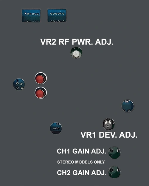
Precision Control: Frequency, Power, and Deviation
Adjusting frequency and power levels is straightforward yet secure. To prevent accidental or unauthorized changes, we have engineered a hardware-based compromise by placing essential controls on the underside of the chassis. By simply sliding the unit out of the rack and inverting it, you gain direct access to the DIP switches and trim pots for precise calibration.
This professional design ensures that critical broadcast parameters—including frequency, power output, and FM deviation—remain exactly where you set them. This manual configuration method offers a layer of physical security that software-only buttons cannot match, protecting your station from inadvertent interference or regulatory violations.


 An incorrect antenna and /or bad feeder cable connections can cause RF burns and levels of RF exposure above the recommended limits for personnel
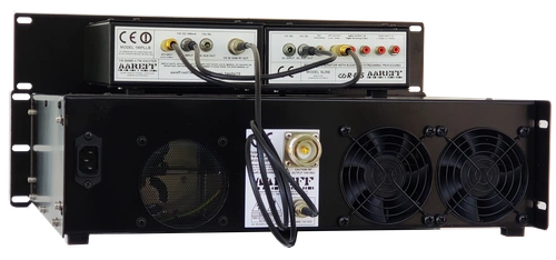

 Do not adjust any factory set internal controls.