 +1 829 698 0733
What Do You Need? Talk To Us
+1 829 698 0733
What Do You Need? Talk To Us8am-4pm EST/NY Monday-Friday info@aareff.com

User Manual and Installation of 1000W (1KW) EIRP System
INTENDED USE
i. The various pieces of equipment in this document are only for use permanently at a pre-defined location with a license or authorisation from the radio spectrum regulator in your country or EU member state.
ii. The installer must have competent RF engineering skills at their disposal, be EMC aware and understand radio frequency systems. The final installation should be in accordance with the site engineering document at https://www.aareff.com/ETR132.pdf The radio station management must assign a responsible person to the transmission equipment and installation.
TRANSMITTER PACKAGE CHECKLIST
| Qty | Description | Item |
| 1 | Tansmitter 90-260V AC 200W FM stero with audio processing |  |
| 1 | IEC AC power cord | 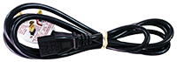 |
| 1 | MPX audio lead | 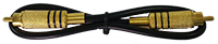 |
| 1 | 30m roll of LMR400 antenna cable | 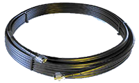 |
ANTENNA PACKAGE CHECKLIST
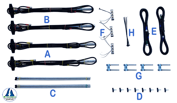
| Qty | Item |
| 2 | A Dipole (YELLOW marked cable + 0.63 cm RG11) |
| 2 | B Dipole (RED marked cable + 0.63 cm RG11) |
| 8 | C 66cm radiator rods |
| 8 | D Bolt, wing nut and plastic spacer |
| 2 | E LMR400 3.54m BLUE / 0.63m RG11 GREEN (Total 4.17m) |
| 3 | F Splitter box |
| 4 | G Mast fixing clamp |
| 20 | H Cable ties |
 IMPORTANT! PLEASE READ, we know it's boring, but if you want your system to work correctly, safely and legally, it is necessary.
The antenna is the most important part of the transmission system and must be correctly installed before proceeding further and before any other transmission equipment is connected.
ANTENNA INSTALLATION AND LAYOUT / CONSTRUCTION. Please go to the 4 Way Stacked Dipole user manual at aareff.com/4tda/en to check all the parts have arrived with you. Then carefully follow the instructions there to install the 4 Way Stacked Dipole. When this is done return here to this document and continue.
IMPORTANT!
FOR THIS SYSTEM TO WORK CORRECTLY AND GIVE 1KW ERIP PLUS TO THE HORIZON IT IS VERY IMPORTANT THAT:
1. THE ANTENNAS ARE MOUNTED STRAIGHT VERTICAL AS SHOWN IN THE USER MANUAL
2. THE ANTENNAS ALL LINE UP WITH EACH OTHER
3. THE LENGTHS OF CABLES SHOULD NOT BE CHANGED IN ANY WAY
INSTALLING THE TRANSMITTER
A) Antenna
 The previous section, ANTENNA is very important, check this has been done. It is self explanatory from the rear panel where the AC power cord is plugged in.
DO NOT plug in the power cord at this stage. Do NOT connect the transmitter to the power cord or the antenna yet.
B) Bottom Panel Controls
Turn the transmitter upside to locate the:
- Power Control VR2 RF PWR. ADJ
- 6 Way Dip Switches S2 and S1
- Deviation Control VR1 DEV. ADJ
- VCO Frequency Lock VC1 FREQ. ADJ
BE CAREFUL not to be too heavy handed, these controls are only small pcb mounted pots and switches and can be damaged with excessive force. You will need to use a small electrical screwdriver to adjust these controls.
C) FIRST !! Set the RF Output to Zero
Adjust VR2 RF PWR. ADJ fully anti-clockwise. In this position the transmitter output is at minimum, basically it has no RF output, it is reduced to zero.
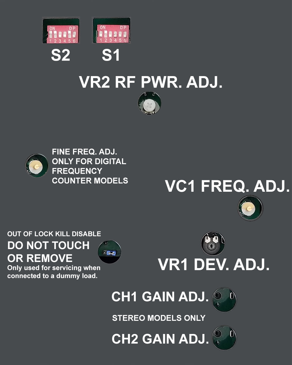
D) Setting the Frequency
Locate the two banks of 6 way dip switches S2 and S1. At the very end of this user manual you can locate the section DIL SWITCH (S2 and S1). This table shows all the frequencies from 87.5 to 108 MHz and the corresponding DIP switch settings. Look up your frequency in the table and then set the tiny dip switches to the ON or OFF position as shown in the table. These switches will determine the start up frequency for the transmitter, so, it's very important they are correct. If they are not correct it's possible to transmit on an unauthorised frequency
Double check again with the table in the Annex that the dip switches are in the correct positions. Make sure they are pushed fully into the ON position or OFF position, not halfway between.
E) Powering the Transmitter
Double check the power is reduced to minimum as described in c) above. At this point the antenna should still be disconnected. Connect the Power Cord to the AC. Select FWD on the front panel switch. Observe the front panel Power Meter. The Power Meter should show zero. If it is not zero, disconnect the AC immediately and double check the power is reduced to minimum as described in c) above.
The Power Meter should light up RED, this may change to BLUE after a few seconds, if it does great, if it doesn't, don't worry at this point, this is also normal.
F) Locking the PLL
It may be by chance that the PLL is close to lock and the Power Meter has lit up in BLUE. If this is not the case and the Power Meter is lit up in RED, then adjust in any direction VC1 FREQ. ADJ. slowly,
PLEASE be careful, this control is delicate. Be patient and continue to turn slowly until the meter lights up BLUE, then STOP turning. The BLUE light indicates PLL lock. The Power Meter should continue to indicate zero, if the Power Meter is showing anything above ZERO, remove the AC and please check again paragraph c) Reducing The RF Output To Zero
G) Connecting the Audio / Baseband
There are three variations of this transmitter, 1: The MPX version; 2: The Stereo version and; 3: The Stereo with Audio Limiting and Processing version.
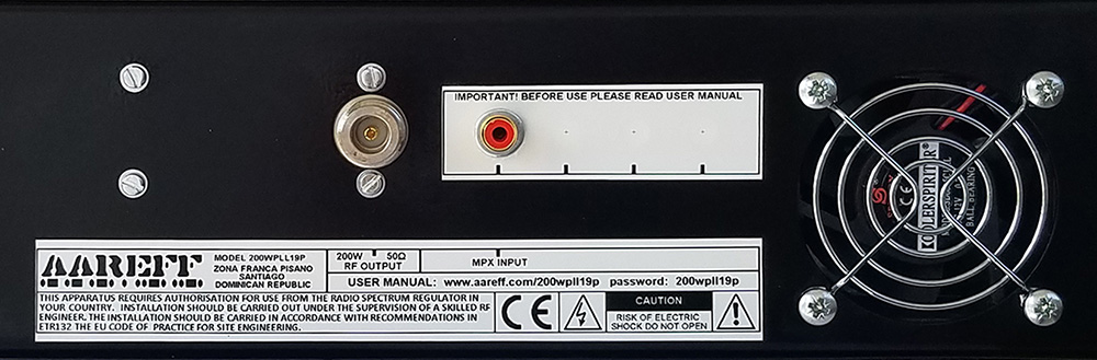
MPX Version
On the MPX version there is just one audio input on the back panel. This is a wide band (30Hz to 76KHz) audio input designed for external processors, stereo and RDS generators
All Stereo Versions
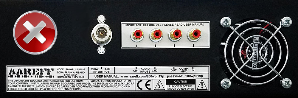
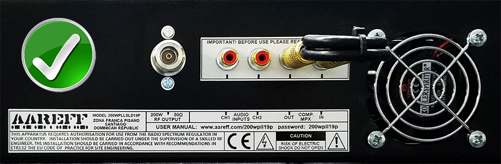
The stereo versions with and without audio processing have the MPX loop IN and OUT on the back panel. For normal operation the MPX OUT needs connecting to the MPX IN with the supplied gold plated RCA/Phono to RCA/Phono cable, like shown in the bottom picture.
This basically connects the internal stereo coder into the MPX input.
If you wish to use an external audio processor or RDS unit that can be inserted in the MPX line between MPX OUT and MPX IN.
H) Checking the Audio Deviation
During manufacture and test the audio deviation will be set broadcast standard line of +8dBu peak for +/-75KHz peak deviation at 88.0 MHz. There is a high possibility that this will not be the same level as the audio source feed from your studio, external audio limiter and/or processing device, MPX stereo generator and/or RDS generator. You need to check this as excessive deviation can cause adjacent channel interference to other users of the radio spectrum.
WITHOUT TEST EQUIPMENT
Audio deviation is difficult to measure without proper test equipment and the method described here cannot replace proper test equipment, however if your regulator permits this method it is possible to check the deviation very close to correct level by using a relative comparison. Use a radio receiver tuned to a known high quality, high budget and reputed radio station. For example in the United Kingdom this would be a national BBC station. Feed the audio output of the radio receiver into some VU meter or level indication on a mixer or other audio equipment. Look carefully at the metering level peaks. You will notice the meter peak constantly at a specific level, make a note of this. Place the antenna of radio receiver as close as possible to your transmitter enclosure. Re-tune the radio receiver to your transmitter frequency. Look at the metering again. Adjust VR1 DEV. ADJ. so that your audio constantly peaks at a little lower than the level you noted. When you have achieved this your deviation is a little lower or close to the legal level. The reason for this setting is that it is legal to under deviate, but not-legal to over deviate, with a lack of test equipment
It is better to be under deviating in order to prevent adjacent channel interference until you have proper test equipment available.
WITH TEST EQUIPMENT
Connect the transmitter via a coupler and dummy load to a Spectrum Analyzer, Modulation Analyzer or Deviation Meter. Adjust VR2 RF PWR. ADJ clockwise. Adjust VR1 DEV. ADJ. for the correct deviation on the test equipment.
I) Setting the Power
Locate the power control VR2 RF PWR. ADJ. If you followed the previous paragraphs, this power control should be fully anti-clockwise. In the fully clockwise position the transmitter RF Output is at maximum. Check the switch on the front panel is set to FWD. Adjust this control to the desired power level. THE TRANSMITTER IS NOW ON AIR!
OPERATION
A) Normal Conditions
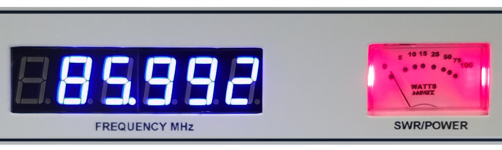
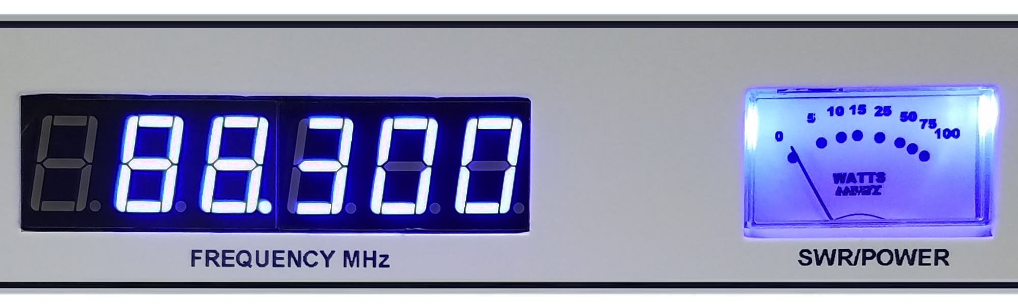
You should hear the cooling fan. The fan draws air into the front and exits the warm air through the rear vents. It is important to keep these vents clear. If you cannot hear the fan turning, then shut the amplifier down by removing the AC mains immediately. The front meter should illuminate in BLUE
B) FWD and REF Switch
The front panel meter should show 200W when the switch is selected to FWD. This is power being sent out of the output socket to the antenna. When REF is selected the power reading ideally should be less than 10W, this means that only 10W or less is being reflected back from the antenna, this is an acceptable and a normal amount. If the power reading is higher than 20W the antenna may need tuning or there may be a problem with the antenna feeder cable or plugs. If the reading is higher than 25W then there is a serious problem with the antenna and you should shut down the power amplifier and investigate the antenna cables, connectors and installation for problems.
IMPORTANT!
ALWAYS KEEP THE VENTS AND FANS CLEAR
SYSTEM SPECIFICATIONS
| Power Supply | 90-260 VAC 50/60 Hz |
| Transmitter RF Power Output | Adj. 10 to 200 Watt into 50 ohms |
| Freq Stability | Better than +/- 1 KHz max. typ. +/-300 Hz |
| Freq Range | 100 KHz steps from 87.5 to 108 MHz |
| Deviation Sensitivity Stability | +/- 2 % max |
| Spurious Emissions | Better than -75dB ref to carrier |
| Harmonic Emissions | Better than -70dB ref to carrier |
| RF Bandwidth | 200 KHz (+/-100 KHz @ -40 dB rtc) |
| Output Connectors | N type 50 ohm (or optional SO239) |
| RF Ruggedness | Any VSWR any phase any length of time |
| Audio Input Sensitivity | 0 dBu 775 mV rms adjustable |
| Audio Inputs Connector | Phono/ RCA socket |
| Audio S/N Ratio | Better than 70 dB |
| Audio Freq Response | 30 Hz to 15 KHz +/- 0.5 dB |
| Audio Distortion | Better than 0.1 % at +/-75 KHz dev |
| Stereo Crosstalk | 35 dB |
| Pre-emphasis | 50 uS (75 uS USA) or None |
| Pilot Tone Freq | 19 KHz |
| Pilot Tone Stability | 0.2 Hz |
| Antenna Polarisation | Vertical |
| Antenna Gain | (0.9λ 2.8 mt spacing at 98 MHz) 6.6 dB + (Isotropic Gain) 2.1 dBi = 8.7 dBi |
| Antenna Cable Loss | -1.2 dB 30m LMR400 foam cable |
| Antenna RF Power Output | 4498 Watts EIRP +/- 0.5 dB (total system gain +7.5 dBi) from -20 to +40 Deg C using 30m of LMR400 foam antenna cable and the four half wave antennas supplied spaced at 0.9λ at 98 MHz |
EQUIPMENT COMPLIANCE (DECLARATION OF CONFORMITY)
European Union
We hereby declare that this equipment complies with;
■ ETS 300384 European Telecommunications Harmonised Standard when used with an audio compressor limiter supplied and tested by Aareff
■ EN 301489-11 V1.3.1 (2006-05) EMC Electromagnetic Compatibility when used with 1 meter AC mains cord supplied. If the installation engineer needs to extend this cord, this and the audio input cable should be no more than 3 meters in length to remain in compliance with EMC directive.
■ 2006/95/EC Directive (2006-12) LVD Low Voltage Directive.
Equipment compliance is possible using equipment from and in conjunction from other manufacturers, but since this is beyond the control of Aareff Systems, Aareff Systems cannot or be expected to guarantee compliance in this situation.
United States
The following list are the FCC technical requirements for FM broadcasting. We confirm and verify that this transmitter complies with the technical requirements.
47 CFR Chapter I Federal Communications Commission sections:
■ 73.1560, 2.1046 RF Power
■ 73.1545, 2.1055 Frequency Stability
■ 73.317, 2.1049 (e)(3) Emission Limitation, Emission Mask
■ 73.317, 2.1057, 2.1051 Emission Limits, Spurious Emissions at Antenna Terminal
■ 73.317, 2.1057, 2.1053 Emission Limits, Field Strength of Spurious Emissions
ROHS
All components used in this apparatus are RoHS compliant and do not contain above the specified limits in any of the following restricted substances:
■ Lead
■ Hexavalent Chromium
■ Mercury
■ Cadmium
■ Polybrominated Biphenyls (PBB's)
■ Polybrominated Diphenylethers (PBDE's)
PRODUCT END OF LIFE
This apparatus must NOT be disposed of with other domestic waste.
We are fully committed to maintaining our responsibilities to the environment. Owners of apparatus that has reached the end of it's useful life can return it to us for recycling, recondition, reuse or proper disposal. You will be required to pay lowest cost postal service available to ship the apparatus to us. Before shipping please contact us for more important information.
LEGAL ADVICE
It is the customer's responsibility to check relevant laws, directives, regulations and licensing requirements before putting this product into service with an antenna system. You, the customer agree to defend, indemnify and hold harmless Aareff Systems Limited, it's employees and agents, from and against any claims, actions or demands, including without limitation legal and accounting fees, alleging or resulting from improper or unlawful use of this product.
NEED TO BUY ONE?
© 2017 AAREFF SYSTEMS LIMITED
ALL RIGHTS RESERVED. Aareff is a trademark of Aareff Transmission Systems. All contents of this document including, but not limited to the images, logos, text, illustrations are protected by copyrights, trademarks and other intellectual property rights which are owned and controlled by Aareff Transmission Systems or by other parties that have licensed their material to Aareff Transmission Systems. This document in part or whole may not be copied, reproduced, republished, uploaded, posted or distributed in any way, including by e-mail, ftp or any other electronic means
Every care has been taken in the preparation of this document, errors in content, typographical or otherwise, may have occurred. If you have comments concerning its accuracy, please contact Aareff Systems Limited (UK)


