8am-4pm EST/NY Monday-Friday info@aareff.com

User Manual - Original and Genuine Veronica® Stereo Coder (SCM)
INTENDED USE
This product is designed and intended for use with a CE/EU marked or FCC compliant transmitter with a MPX baseband audio input of 30 Hz to at least 53 KHz. It should not be used standalone without any enclosure. It is intended to be a: installed inside a broadcast transmitter with other circutry or; b: if used as a stand alone unit, it should be installed in a fully screened EMC enclosure with all input and output connections EMC supressed.
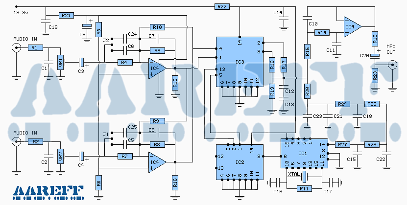
The circuit electronically combines two audio input channels into a single audio output channel usually called Multiplex or MPX. Feeding this MPX into a baseband input at line level (+4dBu) of an FM broadcasting transmitter produces FM Stereo on suitable receivers.
CONSTRUCTION DETAILS
Before attempting any construction, check all the components against the component list. If any of the components are missing or damaged, immediately contact Veronica Kits or your supplier before going any further with this kit. If you are unsure about soldering, see the 'Soldering Tips' section.
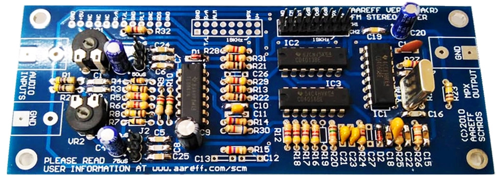
The PCB is printed with a legend showing the component shapes and reference numbers (R1, R2, R3, C1, C2, etc). Use the legend together with the component list to find the correct component for the PCB. Take extreme care when placing the components on the PCB. If a component is incorrectly placed, the circuit will not work properly and may even be damaged.
Most of the ceramic capacitors are the surface mount type and these should have been already soldered in. It's normal to assemble the PCB with the smaller components first, progressing through to the larger components. Use the PCB legend as a positioning aid, solder the components into the board and trim back the excess leads in the following order.
1. Resistors.
Flat to PCB with very short leads.
2. Integrated Circuits (IC).
CAUTION STATIC SENSITIVE DEVICES. (Soldering Iron must have good earth. Avoid touching the IC pins with your fingers). Gently bend IC pins with small pliers to allow fit to PCB. Make sure all pins go into PCB and IC is flat down.
Line up with legend for correct polarity. The IC pins are close together, take great care not bridge any of the pins with solder.
3. Variable Resistors.
Keep leads very short and components close to PCB.

4. XTAL, J1, J2 and Electrolytic Capacitors.
Line up Electrolytic Capacitors with legend for correct polarity. All flat to PCB with no leads showing at all. Flat to PCB

5. Phono Sockets.
Before applying a power supply to the circuit, check and double check that all the components are in the correct position with the right polarisation. Check all the soldered joints, these should be shiny in appearance and all components should be rigid. Look carefully for accidental solder bridges and shorts. When all the checks are complete and okay, test the circuit.
COMPONENT LIST
| R1 | 47R | yellow purple black gold |
| R2 | 47R | yellow purple black gold |
| R3 | 100K | brown black yellow gold |
| R4 | 47K | yellow purple orange gold |
| R5 | 4.7K | yellow purple red gold |
| R6 | 4.7K | yellow purple red gold |
| R7 | 47K | yellow purple orange gold |
| R8 | 100K | brown black yellow gold |
| R9 | 1.2M | brown red green gold |
| R10 | 1.2M | brown red green gold |
| R11 | 100K | brown black yellow gold |
| R12 | 4.7K | yellow purple red gold |
| R13 | 1K | brown black red gold |
| R14 | 27K | red purple orange gold |
| R15 | 27K | red purple orange gold |
| R16 | 4.7K | yellow purple red gold |
| R17 | 4.7K | yellow purple red gold |
| R18 | 4.7K | yellow purple red gold |
| R19 | Not Fitted | |
| R20 | 15K | brown green orange gold |
| R21 | 100R | brown black brown gold |
| R22 | 100R | brown black brown gold |
| R23 | 100K | brown black yellow gold |
| R24 | 4.7K | yellow purple red gold |
| R25 | 4.7K | yellow purple red gold |
| R26 | 3.9K | orange white red gold |
| R27 | 4.7K | yellow purple red gold |
| R28 | 4.7K | yellow purple red gold |
| R29 | 4.7K | yellow purple red gold |
| R30 | 6.8K | blue grey red gold |
| R31 | 1K | brown black red gold |
| R32 | 4.7K | yellow purple red gold |
| D1* | 5V1 | 5.1V zener diode |
| D2* | 11V | 11V zener diode |
| C1 | 100 pF | 101 |
| C2 | 100 pF | 101 |
| C3* | 10 uF | 10 uF 16v |
| C4* | 10 uF | 10 uF 16v |
| C5 | 1 nF | 102 |
| C6 | 1 nF | 102 |
| C9* | 220 uF | 220 uF 16v |
| C7 | 100 pF | 101 |
| C8 | 100 pF | 101 |
| C10 | 100 pF | 101 |
| C11 | 68 pF | 68 |
| C12 | Not Fitted | |
| C13 | Not Fitted | |
| C14 | 100 nF | 100K 104 |
| C15 | 1.8 nF | 182 |
| C16 | 100 pF | 182 |
| C17 | 33 pF | 33 |
| C18 | 3.3 nF | 332 or 152 + 182 |
| C19 | 1 nF | 102 |
| C20 | 10 uF | 10 uF 16v |
| C21 | 220 pF | 221 |
| C22 | 1.8 nF | 101 |
| C23 | 220 pF | 221 |
| C24 | 1.8 nF | 182 |
| C25 | 1.8 nF | 182 |
| C26 | Not Fitted | |
| C27 | Not Fitted | |
| J1 | 3 Way | Jumper Connector |
| J2 | 3 Way | Jumper Connector |
| VR1 | 10 K | variable resistor |
| VR2 | 10 K | variable resistor |
| XTAL | 4.864 MHz | |
| IC1* | 4060B | 4060B 16 pin |
| IC2* | 4013B | 4013B 14 pin |
| IC3* | 4016B | 4016B 14 pin |
| IC4* | TL074 | TL074 14 pin |
| 3 x | Gold Phono Socket | |
| 1 x | DC Connector RED/BLACK | |
| 1 x | SCMRDS PCB | |
 IMPORTANT!
* POLARISED COMPONENTS TAKE GREAT CARE TO INSERT THE COMPONENT LEADS INTO THE PCB THE CORRECT WAY.
SCHEMATIC
CIRCUIT TESTING
Select the correct Pre-Emph for your country using Jumpers on J1 and J2.
 IMPORTANT! DO NOT EXCEED 16 VOLTS DC.
Arrange a regulated power supply or a battery with a voltage between 11 and 16 volts for the circuit. Make the power connection to the PCB using the supplied connector with the red and black wire coming from it.
Connect the MPX OUTPUT to the transmitter input. On Veronica or Aareff transmitters, adjust the audio input level to mid position. Apply a stereo audio source of about line level (775 mV rms) to phono input sockets of the Stereo Coder. Adjust VR1 and VR2 on the Stereo Coder to mid position.
Apply power to the Stereo Coder and Transmitter. Tune an FM Stereo Receiver in to the Transmitter. Your stereo audio source is now 'ON AIR'. The stereo indicator should be active on the FM Receiver. Experiment with the VR1 and VR2 adjustments on the Stereo Coder for the correct levels of audio.
SPECIFICATION
◙ Audio Inputs Standard Line 0dBu 775mV adjustable ◙ PCB Mounted Input and Output Audio Phono ◙ RCA Type Sockets ◙ Power supply or battery over 11-16V DC ◙ Pre-emphasis 50 or 75 uS ◙ Stereo Crosstalk 35 dB min ◙ Low Audio Distortion, less than 0.01% ◙ Pilot Tone 19 KHz +/-0.2Hz ◙ Low Noise, Audio S/N Ratio Better than 70dB ◙ Audio Response 30Hz to 15KHz +/-0.5dB
DECLARATION OF CONFORMITY
AAREFF TRANSMISSION SYSTEMS SL
AVDA ANDALUCIA 1
LA ALFOQUIA-ZURGENA
04661
ALMERIA
ESPANA.
Paul Hollings
![]()

In Zurgena, Almeria, Spain on 01 of November 2008, the equipment:
Original and Genuine Veronica Stereo Coder (SCM)
Meets the essential requirements of the R&TTE directive and complies with:
- ETS 300384 European Telecommunications Harmonised Standard when used with a transmitter and audio compressor limiter supplied and tested by Aareff
- EN 301489-11 V1.3.1 (2006-05) EMC Electromagnetic Compatibility when used with 1 meter AC mains cord supplied. If the installation engineer needs to extend this cord, this and the audio input cable should be no more than 3 meters in length to remain in compliance with EMC directive.
ROHS
All components used in this apparatus are RoHS compliant and do not contain above the specified limits in any of the following restricted substances:
- Lead
- Hexavalent Chromium
- Mercury
- Cadmium
- Polybrominated Biphenyls (PBB's)
- Polybrominated Diphenylethers (PBDE's)
PRODUCT END OF LIFE
This apparatus must NOT be disposed of with other domestic waste.
We are fully committed to maintaining our responsibilities to the environment. Owners of apparatus that has reached the end of it's useful life can return it to us for recycling, recondition, reuse or proper disposal. You will be required to pay lowest cost postal service available to ship the apparatus to us. Before shipping please contact us for more important information.
LEGAL ADVICE
We sell this equipment to professionals and organizations in good faith it will be used correctly and legally. Nearly every country in the world require licensing for this type of equipment. It is the customer's responsibility to check relevant laws, directives, regulations and licensing requirements before installing or putting this product into service with an antenna system. You, the customer or user agree to defend, indemnify and hold harmless Aareff Systems Limited, it's employees and agents, from and against any claims, actions or demands, including without limitation legal and accounting fees, alleging or resulting from improper or unlawful use of this equipment.
BUY ONE
© 2026 AAREFF SYSTEMS LIMITED
ALL RIGHTS RESERVED. Aareff is a trademark of Aareff Transmission Systems. All contents of this document including, but not limited to the images, logos, text, illustrations are protected by copyrights, trademarks and other intellectual property rights which are owned and controlled by Aareff Transmission Systems or by other parties that have licensed their material to Aareff Transmission Systems. This document in part or whole may not be copied, reproduced, republished, uploaded, posted or distributed in any way, including by e-mail, ftp or any other electronic means
Every care has been taken in the preparation of this document, errors in content, typographical or otherwise, may have occurred. If you have comments concerning its accuracy, please contact Aareff Systems Limited (UK)


