 +1 829 698 0733
What Do You Need? Talk To Us
+1 829 698 0733
What Do You Need? Talk To Us8am-4pm EST/NY Monday-Friday info@aareff.com

Circular FM Antenna High Power 3kW
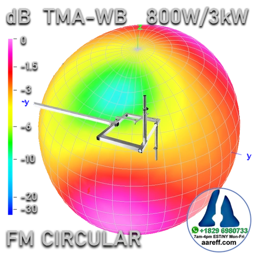
- -0.8dBi Gain
- 3kW HIGH POWER AVAILABLE
- 800W N-Type AVAILABLE
- VSWR ≤ 1.5 AT TUNED FREQUENCY
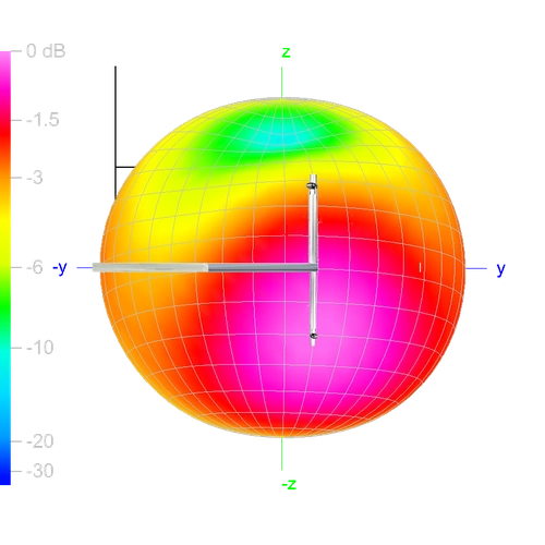
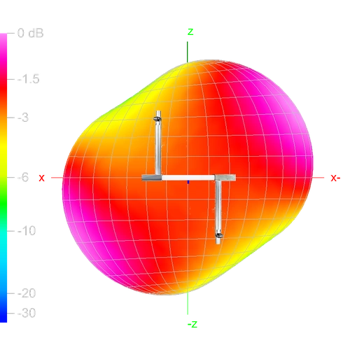
- OMNI DIRECTIONAL
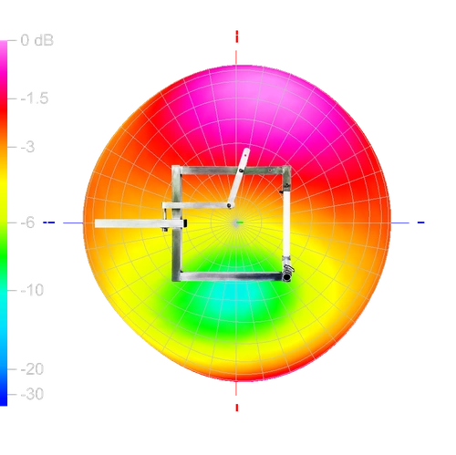
- CIRCULAR POLARIZATION
- AVAILABLE WITH DIN 7-16 CONNECTOR
- LIGHTWEIGHT AT UNDER 3Kg
- EASY ASSEMBLING FOR NOVICES
- STAINLESS STEEL OR ALUMINIUM
- PRICE INCLUDES SHIPPING
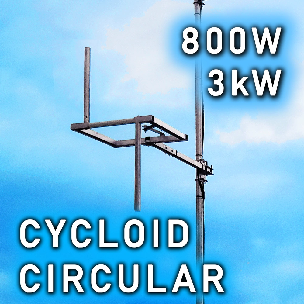
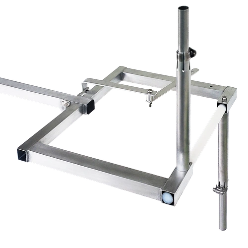
'Cycloid' True Circular Polarization
Aareff High-Power 3kW Circular FM 'Cycloid' Antenna System: Penetrating Signal for Tough Terrains
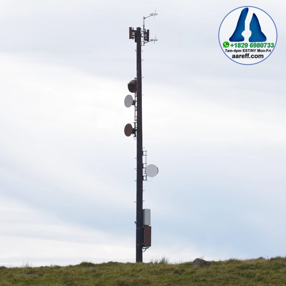
The Aareff 'Cycloid' True Circular Polarization FM Antenna is engineered for professional broadcasters who need exceptional signal performance, especially in challenging geographic areas like The United States, Mexico's mountainous and hilly regions
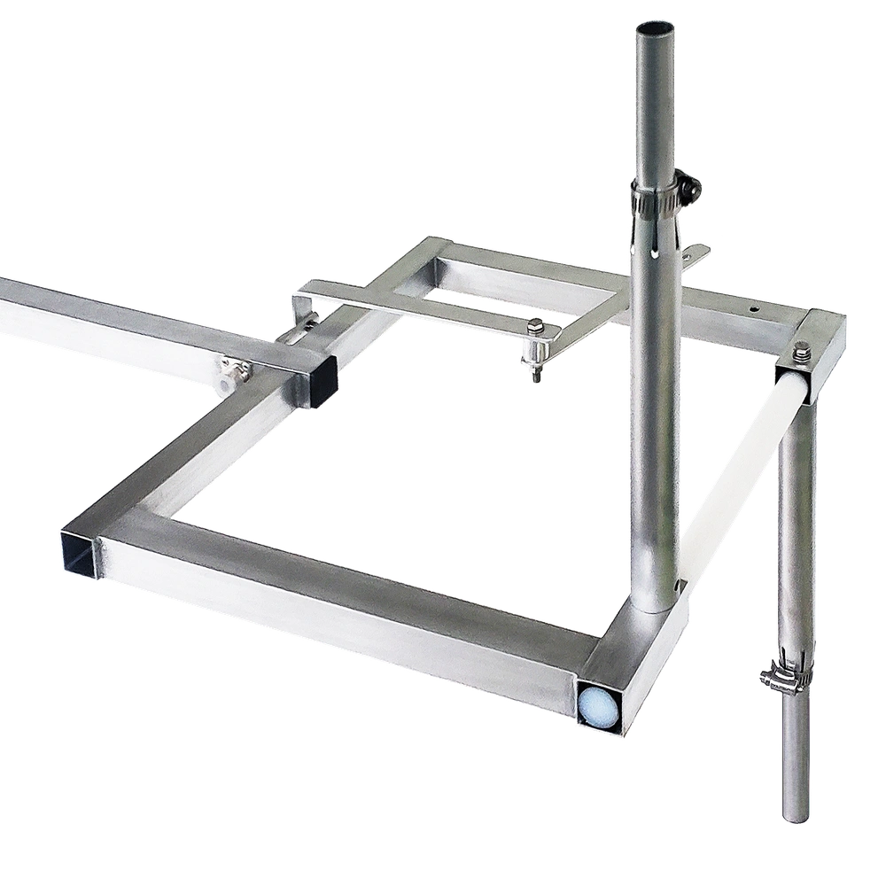
• This unique square-shaped 'cycloid' antenna delivers true circular polarization—a crucial feature that allows your FM signal to penetrate better through valleys and over rugged terrain, ensuring maximum coverage where standard signals fail.
• Built to handle immense power, it is available in 800W (N type) or 3kW (DIN-716) configurations and constructed from durable Aluminum or Stainless Steel. This high-power capability and robust construction establish its professional broadcast authority.
• Superior Signal Penetration: True circular polarization ensures your signal reaches listeners in mountainous, remote, and urban canyon areas of Mexico and similar geographies.
Experience true circular polarization and immense power handling with the Aareff 'Cycloid' antenna. Designed for professional FM broadcasting, this high-performance, omni-directional antenna offers superior signal quality and coverage.The square-shaped Aareff 'Cycloid' True Circular Polarization FM Antenna is engineered to provide maximum performance and durability for any modern FM broadcasting setup.
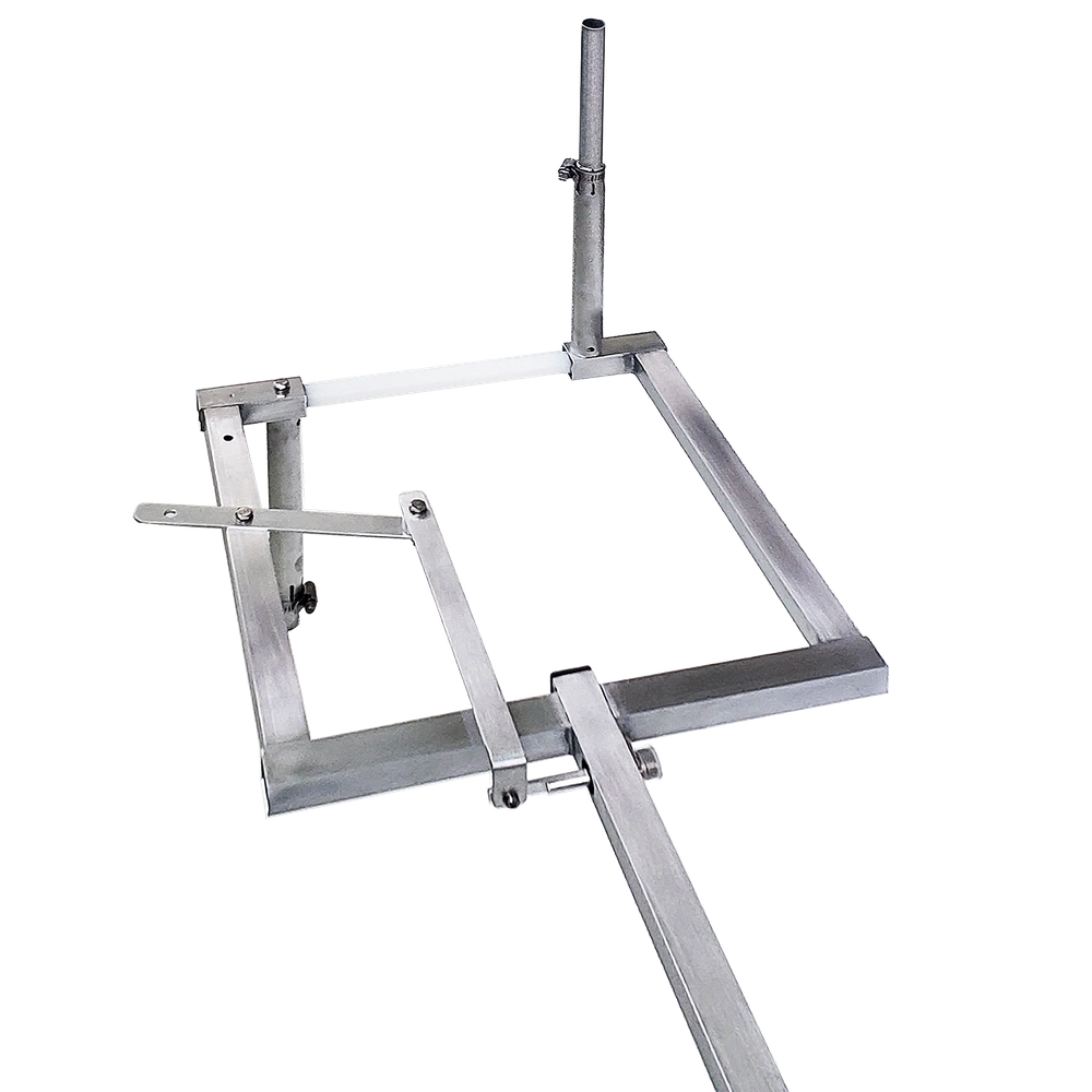
Wideband Tunable From 87 to 108 MHz
The antenna is Wideband Tunable From 87 to 108 MHz. Full wideband frequency tuning is easy using a tuning bar with two distinct positions: one for 87 to 98 MHz and the other for 98 to 108 MHz.
• The tuning bar selects the bottom or top half of the 87 to 108 MHz band.
• Vertical tubes are then adjusted in length to reach the exact frequency.
• A VSWR of less than 1.3 can be expected at the chosen frequency.
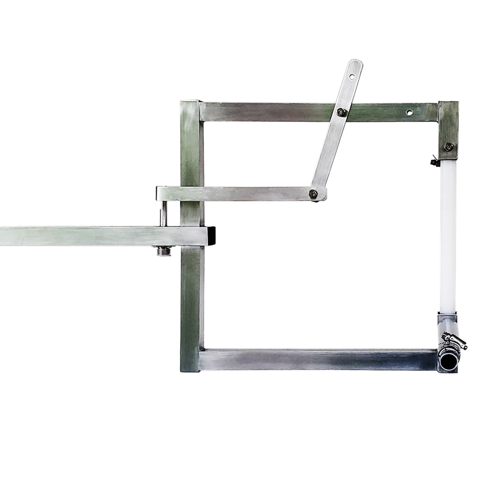
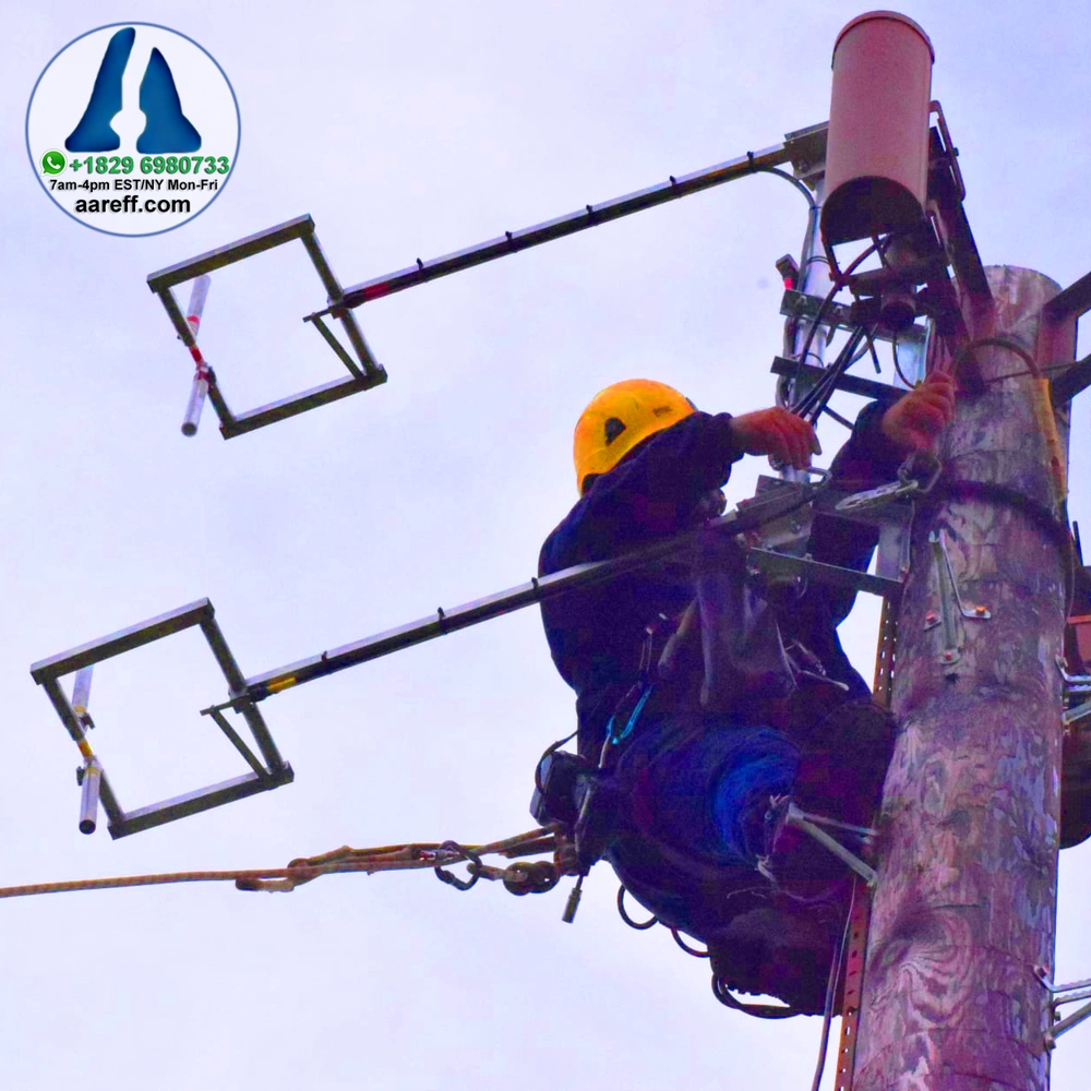
Stacking for High Gain
The Aareff 'Cycloid' True Circular Polarization FM Antenna system is engineered to provide maximum performance and durability for any modern professional FM broadcasting setup. It offers superior signal quality and omni-directional coverage while delivering exceptional value on the market.
• Polarization and Power: The unique square-shaped 'cycloid' design achieves true circular polarization and is built to handle immense power. It is available in 800W (N type) or 3kW (DIN-716) configurations and constructed from robust Aluminum or Stainless Steel. This makes it arguably the best value and most robust circular antenna available.
• Vertical tubes are then adjusted in length to reach the exact frequency.
• Wideband Tuning: The antenna is fully wideband tunable from 87 to 108 MHz. Full wideband frequency tuning is made easy using a tuning bar with two positions: one for 87 to 98 MHz and the other for 98 to 108 MHz. The vertical tubes are then adjusted in length to arrive at the exact frequency, with an expected VSWR of less than 1.3.
• High Gain Stacking (ERP): For broadcasters seeking maximum power and coverage, increasing the Effective Radiated Power (ERP) is highly encouraged through stacking this antenna. Stacking 2, 4 and 8 Way Circular Antennasis standard practice, which can be accomplished using traditional splitters or by driving each antenna from separate amplifiers up to 3kW each. For example, stacking eight of these antennas, each driven by a 3kW amplifier, achieves a powerful radiated circular polarized signal of 150kW EIRP or 90kW ERP, representing the maximum practical size for FM broadcasts.
Simple Setup.
We understand that time is money. This antenna features an easy assembling design, making it suitable even for novices to install quickly and correctly. Its omni-directional pattern guarantees even signal distribution in a 360-degree radius.
Do You Have A Question?
High Power 3kW: Unmatched Performance.
Capable of handling a massive 3kW (3000 Watt) power load, this antenna ensures your signal is broadcast far and wide with exceptional clarity. The unique cycloid design guarantees true circular polarization, which is crucial for minimizing signal fades (multipath distortion) in urban and rugged terrain, providing a more stable and higher-quality listening experience for your audience.
Do you want cable for your antenna?
| Gain (Isotropic) | -0.8dB dBi |
| Frequency Range | 87 - 109 MHz |
| Bandwidth | +/-2.5 MHz 1.5 VSWR |
| Construction | Aluminum and Teflon |
| RF Connectors | N type / DIN 7-16 |
| Impedance | 50 ohm unbalanced |
| Polarization | Circular |
| Maximum RF Power | 0.8kW / 3kW |
| Weight of Antenna | 2.3Kg / 3.9kg |
| Wind Speed Handling | 90 MPH |


 Incorrect antenna can cause RF burns and levels of RF exposure above the recommended limits for personnel