 +1 829 698 0733
What Do You Need? Talk To Us
+1 829 698 0733
What Do You Need? Talk To Us8am-4pm EST/NY Monday-Friday info@aareff.com

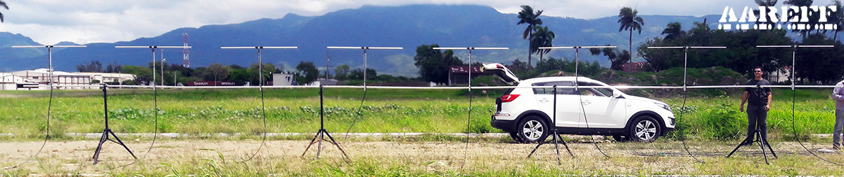
User Manual and Installation of 8 Way Stacked Dipole
IMPORTANT !!!! Please Read
The antenna is the most important part of the transmission system and must be correctly installed before proceeding further and before any transmission equipment is connected.
Ideally this antenna should be mounted at least 20 meters high and clear of any surrounding objects to get maximum range and more importantly to reduce risk of radio frequency radiation to personnel. When mounted at least 20 meters in height off ground and using 400 watts of transmitter power, power flux density measurements made at ground level directly under the antenna show less than 1 W/m2. Several European countries use a value for the power flux density of 10 W/m2 as a basis for considering whether or not an area is safe. The issue of radio frequency radiation limits is a contentious one and work in this field is continuing worldwide. Under no circumstances should the antenna be mounted and used at ground level or within a few meters of personnel.
USER SAFETY RESPONSABILITY
You are responsible for selecting the correct antenna for your application, installing it properly and ensuring the system maintenance.
PACKAGE CHECKLIST
| Qty | Item |
| 4 | YELLOW MARK cable, boom and balun/ transformer |
| 4 | RED MARK cable boom and balun/ transformer |
| 16 | 65cm radiator rods |
| 16 | Bolt, wing nut and plastic spacer |
| 6 | MARK LMR400 5.59m BLUE / RG59 0.53m GREEN (Total Length 6.12m) |
| 7 | Splitter Box |
| 8 | Mast fixing clamp |
| 40 | Cable ties |
TO ERECT THIS ANTENNA YOU WILL NEED TO PROVIDE
| PVC insulation tape and/or Self Amalgamating Tape |
| Tape Measure with mm |
| 13mm Spanner |
| A secure mounting mast with a diameter of 25-37 mm and clear length of at least 16 meters for mounting the dipoles to |
CONSTRUCTION
If possible it's better to assemble this antenna ground level horizontally on like a sub pole of 16m in length and 38mm diameter. Then test it at ground level and when all's verified as working and good, lift the whole antenna assembly up to the tower. It's much easier to find antenna connection problems when the antenna is at ground level. Here's a YouTube video we produced showing the antenna assembled horizontally and being tested for it's directivity. https://www.youtube.com/watch?v=-SnBnkvSTSU
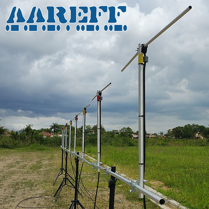
1. Mount the tuned dipoles to the mast using the clamps provided. It is IMPORTANT for correct operation that the dimensions on the diagram are followed as closely as possible, all dipoles must be directly above each other and all 'terminal boxes' must be facing the same way for the system to work properly and give full tuned bandwidth from 88-108MHz.
2. Mount the splitter boxes in numbered order using the tie wraps provided on the mast between the dipoles as shown on the diagram. The splitter boxes are marked top and bottom, make sure top is facing upwards. This is because the plastic enclosure shelters the internal connections from rain and water
3. Connect the four red and four yellow marked dipole antenna cables as shown in the diagram to the outer sockets of splitter boxes numbered 1, 3, 5 and 7. There will be excess cable, simply coil this neatly and tape or tie it to the mast (DO NOT CUT IT BACK AND REFIT THE PLUG). The cables marked with YELLOW, RED, BLUE and GREEN are critical phased lengths and must never be altered in length.
4. Using the first of the six 6 meter cable lengths, connect the BLUE MARKED end to the centre connecter on splitter box 1 and GREEN MARKED end to one of the outer connectors on splitter box 2. There will be excess cable, this is okay, simply coil this neatly and tape or tie it to the mast (DO NOT CUT IT BACK AND REFIT THE PLUG). The cables marked with YELLOW, RED, BLUE and GREEN are critical phased lengths and must never be altered in length.
5. Using the second of the six 6 meter cable lengths, connect the BLUE MARKED end to the centre connecter on splitter box 3 and GREEN MARKED end to one of the outer connectors on splitter box 2. There will be much excess cable, this is okay, simply coil this neatly and tape or tie it to the mast (DO NOT CUT IT BACK AND REFIT THE PLUG). The cables marked with YELLOW, RED, BLUE and GREEN are critical phased lengths and must never be altered in length.
6. Using the third of the six 6 meter cable lengths, connect the BLUE MARKED end to the centre connecter on splitter box 5 and GREEN MARKED end to one of the outer connectors on splitter box 6. There will be much excess cable, this is okay, simply coil this neatly and tape or tie it to the mast (DO NOT CUT IT BACK AND REFIT THE PLUG). The cables marked with YELLOW, RED, BLUE and GREEN are critical phased lengths and must never be altered in length
7. Using the fourth of the six 6 meter cable lengths, connect the BLUE MARKED end to the centre connecter on splitter box 7 and GREEN MARKED end to one of the outer connectors on splitter box 6. There will be much excess cable, this is okay, simply coil this neatly and tape or tie it to the mast (DO NOT CUT IT BACK AND REFIT THE PLUG). The cables marked with YELLOW, RED, BLUE and GREEN are critical phased lengths and must never be altered in length
8. Using the fifth of the six 6 meter cable lengths, connect the BLUE MARKED end to the centre connecter on splitter box 2 and GREEN MARKED end to one of the outer connectors on splitter box 4. There will be much excess cable, this is okay, simply coil this neatly and tape or tie it to the mast (DO NOT CUT IT BACK AND REFIT THE PLUG). The cables marked with YELLOW, RED, BLUE and GREEN are critical phased lengths and must never be altered in length
9. Using the sixth of the six 6 meter cable lengths, connect the BLUE MARKED end to the centre connecter on splitter box 6 and GREEN MARKED end to one of the outer connectors on splitter box 4. There will be much excess cable, this is okay, simply coil this neatly and tape or tie it to the mast (DO NOT CUT IT BACK AND REFIT THE PLUG). The cables marked with YELLOW, RED, BLUE and GREEN are critical phased lengths and must never be altered in length
10. Connect the one end of the main feeder cable to the centre connector on splitter box 4. The other end will go down the tower and connect to the transmitter later.
11. Wrap PVC or self amalgamating tape tightly around and all over the plugs on the splitter boxes to waterproof them.
12. Securely fix the cables using PVC tape or large cable ties to the mast as shown in the diagram opposite. Make sure the cables are not going to flap around in the wind.
13. Make sure that all fixings are tight and are not going to work loose over time with wind.
INPUT RETURN LOSS
RADIATION PATTERN
MAINTENANCE
Because antennas are passive devices maintenance requirements are low, however don't accept low as being none existent, some periodic inspections are required.
Always following a heavy storm or extreme weather condition an inspection should be done and as shown in the table below.
| WEEKS | Building Roof | Light Duty Tower | Heavy Duty Tower |
| 13 |  |
||
| 26 | |
|
|
| 39 | |
||
| 52 | |
|
|
PHYSICAL LAYOUT / CONSTRUCTION

NEED TO BUY ONE?
© 2024 AAREFF SYSTEMS LIMITED
ALL RIGHTS RESERVED. Aareff is a trademark of Aareff Transmission Systems. All contents of this document including, but not limited to the images, logos, text, illustrations are protected by copyrights, trademarks and other intellectual property rights which are owned and controlled by Aareff Transmission Systems or by other parties that have licensed their material to Aareff Transmission Systems. This document in part or whole may not be copied, reproduced, republished, uploaded, posted or distributed in any way, including by e-mail, ftp or any other electronic means
Every care has been taken in the preparation of this document, errors in content, typographical or otherwise, may have occurred. If you have comments concerning its accuracy, please contact Aareff Systems Limited (UK)


