 +1 829 698 0733
What Do You Need? Talk To Us
+1 829 698 0733
What Do You Need? Talk To Us8am-4pm EST/NY Monday-Friday info@aareff.com

User Manual and Installation of 5 GHz Digital STL
PACKAGE CONTENTS CHECKLIST
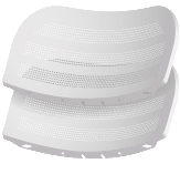
| 2 x Center reflector panel |
 |
| 2 x Pairs of side reflector panels |
 |
| 2 x Feed receiver |
 |
| 2 x Ball joint mount |
 |
| 2 x Metal strap for tube mounting |
 |
| 4 x Set screws |
 |
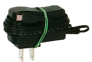
| 5v DC mini-usb AC power supply for Instreamer with correct AC pins |
 |
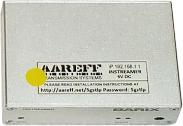
| Barix Instreamer with 192.168.1.1 sticker fitted yellow |
 |
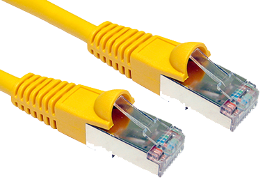
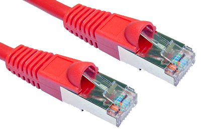
| Cat6 stp/ftp screened network cable marked in yellow |
 |
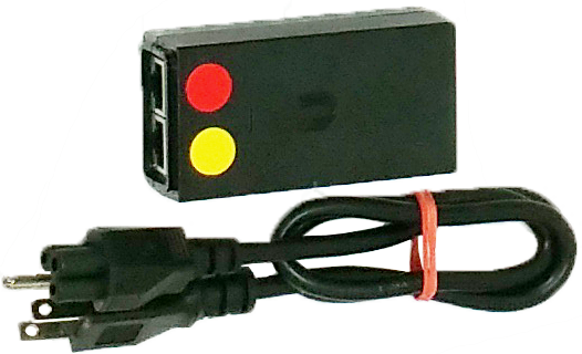
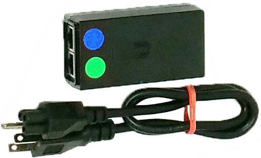
| POE AC power supply and power cable with correct AC pins yellow and red |
 |
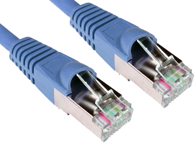
| Cat6 stp/ftp screened network cable marked in red |
 |
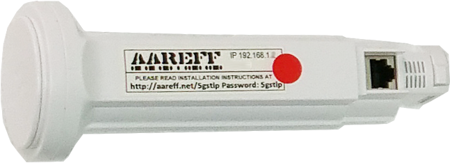
| Send antenna feed with 192.168.1.2 sticker fitted red |
 |
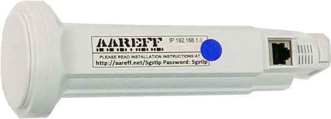
| Receive antenna feed with 192.168.1.3 sticker fitted blue |
 |
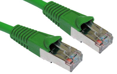
| Cat6 stp/ftp screened network cable marked in blue |
 |
| POE AC power supply and power cable with correct AC pins blue and green |
 |
| Cat6 stp/ftp screened network cable marked in green |
 |
| 12v DC power supply for Exstreamer with correct AC pins |
 |
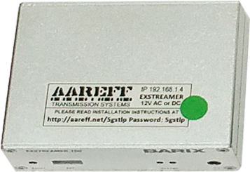
| Barix Exstreamer 100 with 192.168.1.4 sticker fitted green |
 |
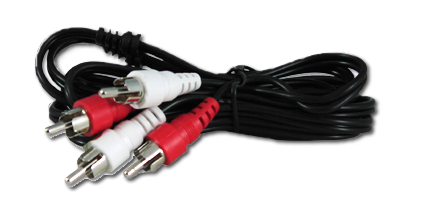
| RCA phono to RCA phono lead |
 |
1st ASSEMBLE THE SEND ACTIVE ANTENNA (192.168.1.2)
This long range active dish antenna is pre-configured as an 'access point' ip address 192.168.1.2. This unit sends the signal up to 15km in the right conditions to be received by another similar active dish antenna.
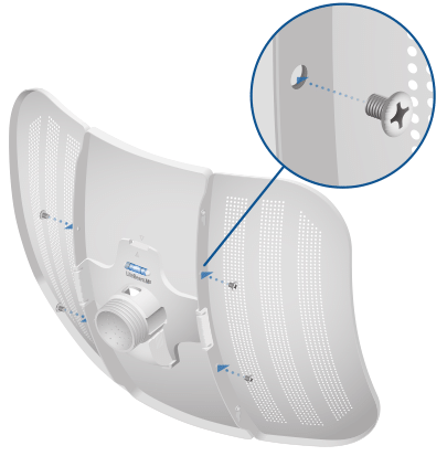
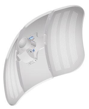
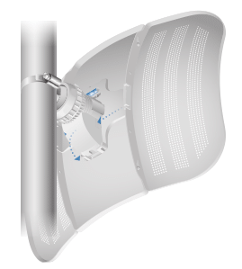
1. Assemble the antenna reflector by attaching the Side Reflector Panels to the Center Reflector Panel:
a. Insert the heads of the two mounting studs on the Center Reflector Panel into the large opening of the slotted holes of a Side Reflector Panel.
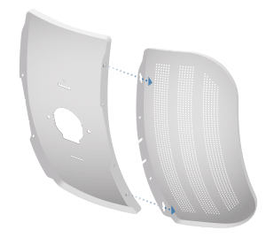
b. Slide the Side Reflector Panel down until the top edges of the panels align. The Side Reflector Panel is captured when both heads of the mounting studs are positioned over the narrow opening of the slotted holes.
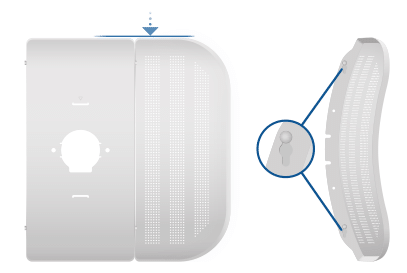
c. Repeat the assembly for the other Side Reflector Panel.
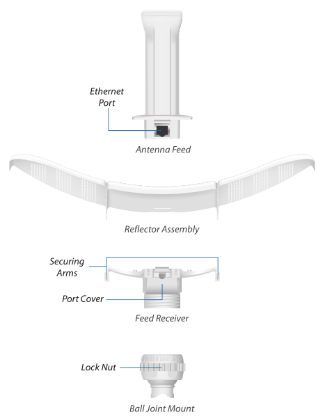
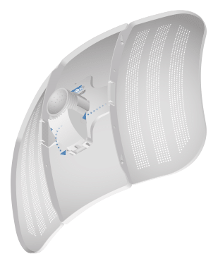
2. Hold the reflector assembly by hand (do not use a table top or flat surface) and insert the Feed Receiver into the reflector assembly to secure the panels:
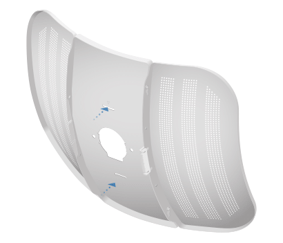
a. Align the arrows on the Center Reflector Panel and the Feed Receiver, and insert both edges of the Side Reflector Panels and Center Reflector Panels into the securing arms of the Feed Receiver.
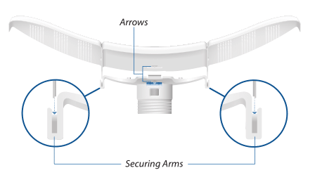
b. Insert the Feed Receiver into the Center Reflector Panel by pressing the top and bottom snap hooks into the slots of the Center Reflector Panel.
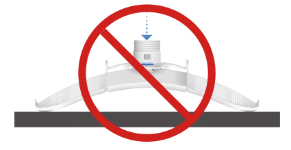
 WARNING!
Do not install the Feed Receiver into the reflector assembly by pushing down onto a table top or other flat surface as this can deform the panels. Hold the reflector assembly by hand.
(Optional) For additional support, attach four M3x4 self tapping screws (not included) to the antenna assembly.
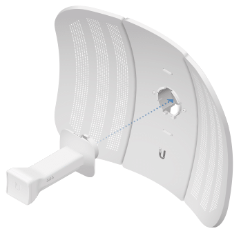
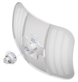
3. Insert the Antenna Feed into the Feed Receiver until the feed locks into place.
4. Press both sides of the Port Cover and detach it from the Feed Receiver.
5. Connect the 30 METRE CAT5/6 STP/FTP SCREENED NETWORK CABLE MARKED RED to the Ethernet Port of the SEND ACTIVE ANTENNA (192.168.1.2). Make sure it's pushed and locked into the hole properly, this is a heavy CAT6 cable and sometimes a little extra push is needed to get it to click into place.
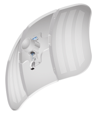
6. Reattach the Port Cover.
2nd INSTALL THE SEND ACTIVE ANTENNA (192.168.1.2)
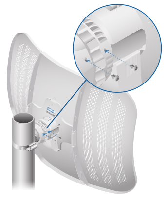
1. Attach the Ball Joint Mount to the Feed Receiver by turning the Lock Nut clockwise by hand. Do not tighten the nut.
2. Open the Metal Strap and feed it through the base of the Ball Joint Mount.
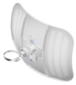
3. Wrap the Metal Strap around the pole. Use a 7 mm socket wrench or screwdriver to turn the screw clockwise and securely fasten the strap to the pole.
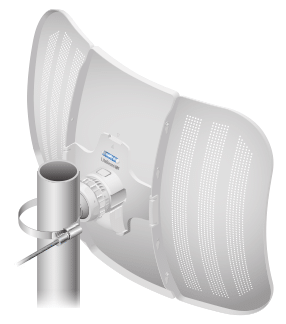
4. Remove the Port Cover and then loosen the Lock Nut on the Ball Joint Mount.
5. Aim the Antenna Feed toward the direction you want your STL. Use the bubble level to ensure level alignment, and then lock the aim by hand?tightening the Lock Nut.
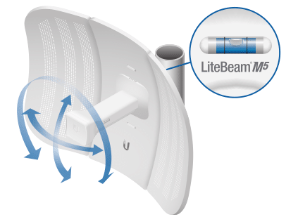
6. Replace the Port Cover.
7. Locate the two holes on the Lock Nut, and fasten a Set Screw into each hole to securely lock the aim.
8. Run the 30 metre cable MARKED RED down to the inside of the studio where the Barix Instreamer is going to be. Connect the 30 metre cable MARKED RED to the POE (Power Over Ethernet) point. It should be held tight against the metal structure of the tower or pole, this will prevent potential interference problems from the main FM transmitter antennas
3rd INSTALL THE STUDIO BARIX INSTREAMER (192.168.1.1)
This unit is pre-configured to stream digital audio from ip address 192.168.1.1.
1. Situate and connect the audio from the studio output directly into LINE IN on this unit.
2. Connect the digital output of this unit to the POE (Power Over Ethernet) point using the 1 metre standard Cat6 cable MARKED YELLOW. This POE adapter mixes the power supply with the digital stream.
3. Connect the POE to the AC electricity supply of 115V, 220 or 240 V
Okay, that is the studio and send active antenna installed and operational. Now go to the main transmitter site or the far other end of the STL.
4th ASSEMBLE THE RECEIVE ACTIVE ANTENNA (192.168.1.3)
When you arrive at the main transmitter site or the far other end of the STL assemble the receive active antenna. Please follow exactly the same process as ASSEMBLING THE SEND ACTIVE ANTENNA, but this time use the 30 METRE CAT6 STP/FTP SCREENED NETWORK CABLE MARKED BLUE instead of the red one.
5th INSTALL THE RECEIVE ACTIVE ANTENNA (192.168.1.3)
Again, Please follow exactly the same process as INSTALLING THE SEND ACTIVE ANTENNA, but this time use the 30 METRE CAT6 STP/FTP SCREENED NETWORK CABLE MARKED BLUE instead of the red one.
The process of alignment is the same as the SEND ACTIVE ANTENNA, but this time aim the Receive Antenna Feed as closely as possible to line up with the Send Antenna back at the studio location. Use the bubble level to ensure level alignment, and then lock the aim by hand tightening the Lock Nut.
Again, replace the Port Cover. Locate the two holes on the Lock Nut, and fasten a Set Screw into each hole to securely lock the aim.
Run the 30 metre cable MARKED BLUE down to the inside of the transmitter building where the Barix Exstreamer is going to be. Then connect it to the POE (Power Over Ethernet) point. It should be held tight against the metal structure of the tower or pole, this will prevent potential interference problems from the main FM transmitter antennas
6th INSTALL THE TRANSMITTER SITE BARIX EXSTREAMER (192.168.1.4)
This unit is pre-configured to ip address 192.168.1.4 and to decode the digital audio stream.
1. Using the 1 metre standard Cat6 cable MARKED GREEN connect the POE to the Exstreamer.
2. Connect the audio LINE OUT from this unit directly into the input of the Aareff Limiter ALSCB or other transmitter input.
When this is complete the Exstreamer, POE and the RECEIVE active dish antenna should be powered.
FINAL CHECK
If the both active antennas SEND and RECEIVE are pointing at each other with no buildings or trees blocking the view between them, then the STL should activate and start working.
PLEASE NOTE!. It takes between 1 and 2 minutes seconds for the whole system to boot up and start transferring audio.
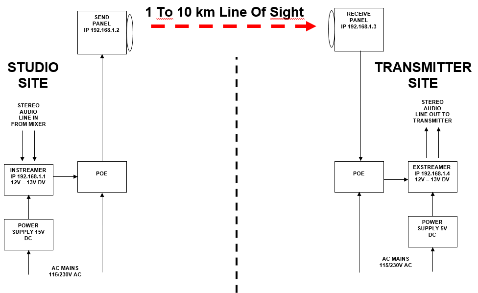
GENERAL SET UP
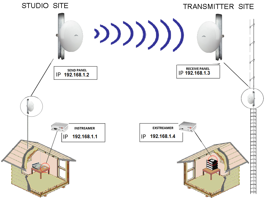
SYSTEM BLOCK DIAGRAM
ACTIVE ANTENNA SPECIFICATIONS
| Dimensions | 347 x 260 x 208 mm |
| Weight | 0.7 kg |
| Operating Frequency | Worldwide 5150 - 5875 MHz USA 5150 - 5250, 5725 - 5850 MHz |
| Networking Interface | 10/100 Ethernet Port |
| Antenna Gain | 23 dBi |
| Max. Power Output | 25 dBm |
| Max. Power Consumption | 4W |
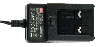
| Power Supply | 25V, 0.2A PoE Adapter |
| Power Method | Passive PoE (Pairs 4, 5+; 7, 8 Return) |
| Wind Survivability | 200 km/h (125 mph) |
| Wind Loading | 176.86 N @ 200 km/h |
| ESD/EMP Protection | ±24kV Contact / Air |
| Shock and Vibration | ETSI300-019-1.4 |
| Operating Temperature | -40 to 70 ºC |
| Operating Humidity | 5 to 95% Noncondensing |
| Certifications | CE, FCC, IC |
LEGAL ADVICE
It is the customer's responsibility to check relevant laws, directives, regulations and licensing requirements before putting this product into service with an antenna system. You, the customer agree to defend, indemnify and hold harmless Aareff Systems Limited, it's employees and agents, from and against any claims, actions or demands, including without limitation legal and accounting fees, alleging or resulting from improper or unlawful use of this product.
BUY ONE
© 2018 AAREFF SYSTEMS LIMITED
ALL RIGHTS RESERVED. Aareff is a trademark of Aareff Transmission Systems. All contents of this document including, but not limited to the images, logos, text, illustrations are protected by copyrights, trademarks and other intellectual property rights which are owned and controlled by Aareff Transmission Systems or by other parties that have licensed their material to Aareff Transmission Systems. This document in part or whole may not be copied, reproduced, republished, uploaded, posted or distributed in any way, including by e-mail, ftp or any other electronic means
Every care has been taken in the preparation of this document, errors in content, typographical or otherwise, may have occurred. If you have comments concerning its accuracy, please contact Aareff Systems Limited (UK)


