8am-4pm EST/NY Monday-Friday info@aareff.com

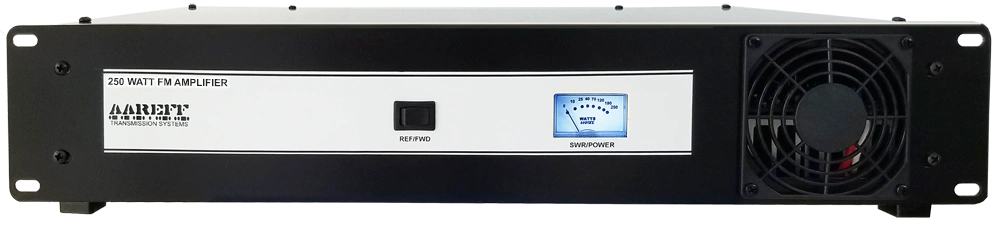
User Manual 250W Band II VHF FM Broadcasting Amplifier
INTENDED USE
i. The equipment in this document is only for use permanently at a pre-defined location with a license or authorisation from the radio spectrum regulator in your country or EU member state.
ii. The installer must have competent RF engineering skills at their disposal, be EMC aware and understand radio frequency systems. The final installation should be in accordance with the EU and the US techincal parameters and the maximum audio deviation level for the full composite MPX signal should be adjusted to b an absoulte maximum for +/-75 KHz.
USA REQUIREMENTS. Section 2.1047 Modulation characteristics and section 2.1049 Occupied bandwidth at:
http://www.gpo.gov/fdsys/granule/CFR-2011-title47-vol1/CFR-2011-title47-vol1-sec2-1047/content-detail.html
EU REQUIREMENTS. Section 8 Audio Processing Limiter at:
https://www.aareff.com/ETR132.pdf
PACKAGE CHECKLIST
| Qty | Description | Item |
| 1 | 250W FM Power Amplifier |  |
| 1 | IEC AC power cord |  |
| 1 | BNC to BNC 50 ohm Cable |  |
USA TECHNICAL REQUIREMENTS
This power amplifier is not suitable or legal to use with LPFM, it is suitable for regular FM broadcasting using an FCC verified or certified exciter.
This power amplifier is not intended for installation by an unqualified end user, the installer must have competent RF engineering skills and EMC knowledge at their disposal. The whole transmission system, including the antenna system, exciter and audio limiting, should be installed in accordance with 47 CFR Chapter I Federal Communications Commission parts; 73.1560, 2.1046 RF Power; 73.1545, 2.1055 Frequency Stability; 73.317, 2.1049 (e)(3) Emission Limitation, Emission Mask; 73.317, 2.1057, 2.1051 Emission Limits, Spurious Emissions at Antenna Terminal; and 73.317, 2.1057, 2.1053 Emission Limits, Field Strength of Spurious Emissions.
EU REGULATORY REQUIREMENTS
This product complies with EMC directive of the European Union. To meet this directive the user or installer must follow the wiring instructions in this user manual
This equipment is not intended for installation by an unqualified end user, the installer must have competent RF engineering skills and EMC knowledge at their disposal. The whole transmission system, including the antenna system, exciter and audio limiting, should be installed in accordance with document ETR132, a copy of this is available at https://www.aareff.com/ETR132.pdf
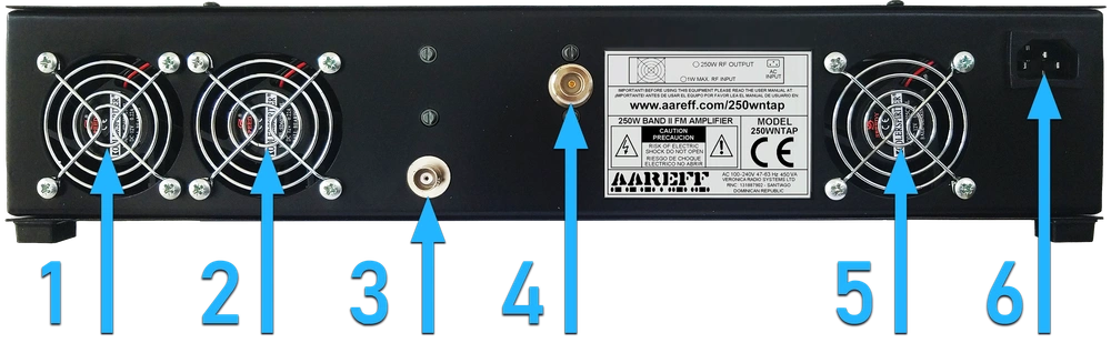
BACK PANEL LAYOUT
| 1 | 2.6W Forced Air Ball Bearing Cooling Fan |
| 2 | 2.6W Forced Air Ball Bearing Cooling Fan |
| 3 | 1W to 1.4W into 50 Ohm RF Input BNC-Male |
| 4 | 250W 50 Ohm RF Output N-Female |
| 5 | 2.6W Forced Air Ball Bearing Cooling Fan |
| 6 | AC Power Connector 90-260V AC 50-60 Hz 480W |
INSTALLING THE POWER AMPLIFIER
DO NOT plug in the power cord at this stage
A) Antenna
 Incorrect antenna can cause RF burns and levels of RF exposure above the recommended limits for personnel
Ideally the antenna for this power amplifier should be at least 2 dipoles stacked and phased, a 5/8 type or other antenna with similar gain or more to the horizon. It should be ideally mounted 20 meters high and clear of any surrounding objects to get maximum range and more importantly to reduce risk of radio frequency radiation to personnel. When mounted at 20 meters in height off ground and using 250 watts of transmitter power, power flux density measurements made at ground level directly under the antennas described above show less than 1 W/m2. Several European countries use a value for the power flux density of 10 W/m2 as a basis for considering whether or not an area is safe. The issue of radio frequency radiation limits is a contentious one and work in this field is continuing worldwide.
UNDER NO CIRCUMSTANCES should the antenna be mounted and used at ground level or within a few meters of personnel.
A tuned antenna that presents 50 ohms with a 50 ohm coaxial cable should be used. This should give a return loss ideally of 16dB (SWR 1.4) or better at the operating frequency. The RF plug should be N type male.
Plug the antenna cable into the amplifier N type female connector. Make sure this is tight as poor and loose connections can cause RF burns to personnel, severe noise to the transmission and excessive RF bandwidth.
B) Amplifier Driver / Exciter
The Driver / Exciter needs to be compliant and set to the correct frequency BEFORE the amplifier is powered by AC Mains
Under NO CIRCUMSTANCES should the amplifier be connected to a Driver / Exciter where the RF output performance and specification is unknown. Such action could be cause serious disturbance to the electromagnetic spectrum and in extreme cases dangerous interference to air navigation and emergency services.
The amplifier requires a suitable driver / exciter with audio limiting and an RF output of between 900mW and 1400mW (MAX) when loaded with 50 ohms. This must also be equivalent, better or meet the specifications shown in European Standard ETS 300 384.
Connect the Driver / Exciter to the power amplifier using the 1m /3ft BNC to BNC RF cable, but DO NOT CONNECT THE AC POWER CORD TO THE AMPLIFIER YET
Before powering up the amplifier the frequency of the Driver / Exciter should be set and checked. If the AC mains is not connected to the power amplifier, it is safe to use the power amplifier BNC input as a dummy load for the Driver / Exciter. At this stage, if possible, it would also be advisable to check the deviation and that the audio of the Driver / Exciter is correct.
C) Powering Up
When you are absolutely sure and you have doubled checked the Driver / Exciter is operating correctly and the antenna is installed and connected correctly, then power up the 250W amplifier by connecting the AC power cord to it.
If you are using a transmitter driver supplied by another manufacturer, compliance cannot be guaranteed. On completion of the installation it is necessary that the engineer checks the RF output of the power amplifier for compliance.
OPERATION
A) Normal Conditions
You should hear the cooling fan, it's quite noisy. The fan draws air into the back and exits the warm air through front panel. It is important to keep these vents clear. If you cannot hear the fan turning, then shut the amplifier down by removing the AC mains immediately. The front meter should illuminate in BLUE
B) FWD and REF Switch
The front panel meter should show 200W or more when the switch is selected to FWD. This is power being sent out of the output socket to the antenna. When REF is selected the power reading ideally should be less than 10W, this means that only 10W or less is being reflected back from the antenna, this is an acceptable and a normal amount. If the power reading is higher than 20W the antenna may need tuning or there may be a problem with the antenna feeder cable or plugs. If the reading is higher than 30W then there is a serious problem with the antenna and you should shut down the power amplifier and investigate the antenna cables, connectors and installation for problems.
C) Power Control
It is possible to reduce the power by reducing the Driver / Exciter if 200W is too much for your application. If you cannot reduce the power of the Driver / Exciter then there is a power control inside the amplifier. If you need to use this, please contact us for advice
BLOCK DIAGRAM
WILKINSON SPLITTER
Two quarter wave lengths of RG179 75 ohm PTFE cable convert the 1W 50 ohm input into two matched 50 ohm outputs of 500mW each.
MRF151 125W RF VCA (Voltage Controlled Amplifier)
This unit is a fully self-contained with heatsink and low pass filter 125W amplifier module block. The 500mW is reduced 250mW using a 3dB pi configured resistor attenuator. The 3dB of resistive loss completely dampens the input reactance variations of the SD1127 RF driver transistor in the module and provides the Wilkinson splitter a good resistive load to work into. In addition, this resistive load prevents parasitic oscillations starting in the amplifier and allows any random length of 50 ohm input cable to be used with the amplifier without fear of any RF instability.
Together the SD1127 RF driver transistor and the MRF151 Mosfet are matched to each other and provide a total gain of 27dB increasing the 250mW to 125W.
The DC gate bias voltage of the MRF151 is decoupled and used as the DC control for the RF gain making the amplifier module a fully stable VCA.
A thermistor located very close to the heatsinks in conjunction with a comparator produces a feedback voltage that is returned to DC control for the RF gain. This reduces the power of the 125W amplifier to a level that prevents the heatsink exceeding 70C. This will only happen if the amplifier cooling fans fail, or the cooling vents are blocked.
A 10 pole RF low pass filter is integrated into each amplifier module which provides greater than 75dB of suppression at the worst 88 MHz harmonic of 176 MHz. This complies with the technical standards of the United States FCC and the harmonised standards of the European Union.
WILKINSON COMBINER
Two quarter wave lumped elements L and C of 75 ohms are used in the Wilkinson configuration to combine the outputs of the two 125W RF VCA's to output 250W.
SWR BRIDGE
At the final output, just before the RF output socket the SWR bridge (directional coupler) with a directivity of at least 20dB provides DC voltages that represent forward and reflected power. These voltages are fed to comparators which are set to output a feedback control voltage if the forward and reflected power exceeds 250W and 20W respectively. The control voltage is returned to the DC control of two 125W amplifier modules reducing the gain and output power.
Under severe reflected power such as open circuit or short circuit applied directly to the output socket, the 125W amplifier modules will only output a maximum voltage which corresponds to 10W each at 50 ohms. This provides a safe margin to prevent damage to the two MRF151s, output matching and low pass filter capacitors.
4W RF VCA (Voltage Controlled Amplifier) WITH LPF
This amplifier first reduces the 1W input to 400mW using a pi configuration 4dB resistor attenuator. The 4dB of resistive loss completely dampens the input reactance variations of the SD1127 RF transistor and prevents parasitic oscillations starting in the amplifier. Due to this any random length of 50 ohm input cable can be used with the amplifier without fear of any RF instability.
The output power can be varied between 0 and 4W using a DC control voltage. This is achieved by varying the voltage to the feed choke on the collector of the SD1127 RF transistor. An onboard DC power regulator transistor takes care of this voltage.
1000W RF AMP. BLF188XR
With 24dB of gain the LDMOS BLF188XR provides 1000W of output with up to 80% efficiency. A thermistor buried in the heatsink in conjunction with a comparator produces a feedback voltage that reduces the power of the 4W VCA driver and in turn the 1000W output to a level that prevents the base plate from exceeding 70C. This will only happen if the amplifier cooling fans fail, or the cooling vents are blocked.
LOW PASS FILTER
Four silver plated large #8AWG coils and a Teflon PCB form the 9th order Chebyshev filter. At 176MHz the harmonic of 88MHz the filter provides -47dB rejection. The 1000W amplifier module has at least 35dB rejection of 176MHz. The two added together (35 + 47) provide a total harmonic rejection of over 80dB. This exceeds that required by the United States FCC and the European Union Harmonised Standard. Each filter is carefully sweep tested with a HP8753ES network analyzer.
SWR BRIDGE
At the final output, just before the RF output socket the SWR bridge (directional coupler) with a directivity of at least 20dB provides proportional DC voltages that represent forward and reflected power. These voltages are fed to comparators which are set to output a feedback control voltage if the forward and reflected power exceeds 1000W and 40W respectively. The control voltage reduces the power of the 4W VCA driver and in turn the output of the 1000W amplifier module.
Under severe reflected power such as open circuit or short circuit applied directly to the output socket, the 1000W amplifier module will only output a maximum voltage 44V rms which corresponds to 40W at 50 ohms. This provides a safe margin to prevent damage to the LDMOS BLF188XR, output matching and low pass filter capacitors.

MAINTENANCE
The only maintenance the amplifier needs is some periodic cleaning. Following a number of weeks of continuous 24/7 use (specified below), the amplifier should be shut down and disconnected. A technician or engineer needs to take of the top lid by removing the self tapper screws. Using a soft new and clean paint brush with a vacuum clean hose, the dust should be gently brushed and sucked away from all areas inside. Pay particular attention to the actual fans at the rear and the fan vent at front.
The table below shows the recommended number of weeks cleaning should be done for some typical environmental areas.
| WEEKS | SALTY | SANDY | DUSTY | PUBLIC | CLEAN |
| 4 |  |
||||
| 6 | |
|
|||
| 8 | |
||||
| 12 | |
 Do not adjust any factory set internal controls.
Under NO CIRCUMSTANCES should any adjustments be made to the internal controls. Such adjustments could damage the unit and invalidate the warranty and also cause serious interference to other users of the electromagnetic spectrum.
TECHNICAL DATA
(All stated measurements were made at 220VAC at 27 Degrees Celsius ambient temperature unless stated)
RF and AF Parameters
| Power Output Adj. | Adjustable from 0 to 250 Watts into 50 ohms |
| Freq Range | 87.5 to 108 MHz |
| Spurious Emissions | Less than -75 dB ref to carrier |
| Harmonic Emissions | Less than -70 dB ref to carrier |
| Residual AM | Less than 0.5 % |
| Synchronous AM | Less than 0.5 % |
| RF Output Connector | N-Female |
| RF Ruggedness | Any VSWR, phase, length of time |
| Operating Temp | -20 to +40 Deg C |
AC Mains Parameters
| Input Voltage | 88 ~ 264VAC 47 ~ 63Hz 127 ~ 370VDC |
| Input Power | 480W max. for 250W RF OUT with RF SWR 1.5 or less |
| Power Factor | 0.95/230VAC 0.98/115VAC at full load |
| Working Humidity | 20 ~ 90% RH non-condensing |
| Safety Standards | UL60950-1, TUV EN60950-1 Approved |
| EMC Conduction & Radiation | Compliance to EN55022 (CISPR22) Class B |
| EMC Harmonic Current | Compliance to EN61000-3-2,-3 |
| EMC Immunity | Compliance to EN61000-4-2,3,4,5,6,8,11; ENV50204, Light industry level, criteria A |
Physical Parameters
| Material | Black powder coated 16 gauge mild steel |
| Dimensions | |
| Weight |
EQUIPMENT COMPLIANCE (DECLARATION OF CONFORMITY)
Aareff Systems Limited can only guarantee compliance with ETS 300384 European Telecommunications Harmonised Standard and FCC Technical Requirements 47 CFR Chapter I part 73 when used with:
- A driver / exciter supplied and tested by Aareff Systems Limited.
- An audio compressor limiter supplied and tested by Aareff Systems Limited.
Equipment compliance is perfectly possible and normal using equipment in conjunction from other manufacturers, but since this is beyond the control of Aareff Systems Limited, Aareff Systems Limited cannot ultimatly guarantee the compliance.
European Union
We hereby declare that this equipment complies with;
- ETS 300384 European Telecommunications Harmonised Standard when used with a compliant audio compressor limiter and driver / exciter
- EN 301489-11 V1.3.1 (2006-05) EMC Electromagnetic Compatibility when used with 1 meter AC mains cord supplied. If the installation engineer needs to extend this cord, this and the audio input cable should be no more than 3 meters in length to remain in compliance with EMC directive.
- 2006/95/EC Directive (2006-12) LVD Low Voltage Directive.
United States
This equipment has not been independently tested by an FCC recognised listed laboratory and for this reason it is not classified as certified. The following list are the technical requirements for the whole transmission system including this equipment and other equipment we may not supply. We hereby declare and verify that this equipment when used with a compliant audio compressor limiter and driver / exciter complies with the following FCC technical requirements
47 CFR Chapter I Federal Communications Commission parts:
- 73.1560, 2.1046 RF Power
- 73.1545, 2.1055 Frequency Stability
- 73.317, 2.1049 (e)(3) Emission Limitation, Emission Mask
- 73.317, 2.1057, 2.1051 Emission Limits, Spurious Emissions at Antenna Terminal
- 73.317, 2.1057, 2.1053 Emission Limits, Field Strength of Spurious Emissions
LEGAL ADVICE
We sell this equipment to professionals and organizations in good faith it will be used correctly and legally. Nearly every country in the world require licensing for this type of equipment. It is the customer's responsibility to check relevant laws, directives, regulations and licensing requirements before installing or putting this product into service with an antenna system. You, the customer or user agree to defend, indemnify and hold harmless Aareff Systems Limited, it's employees and agents, from and against any claims, actions or demands, including without limitation legal and accounting fees, alleging or resulting from improper or unlawful use of this equipment.
ROHS
All components used in this apparatus are RoHS compliant and do not contain above the specified limits in any of the following restricted substances:
- Lead
- Hexavalent Chromium
- Mercury
- Cadmium
- Polybrominated Biphenyls (PBB's)
- Polybrominated Diphenylethers (PBDE's)
PRODUCT END OF LIFE
This apparatus must NOT be disposed of with other domestic waste.
We are fully committed to maintaining our responsibilities to the environment. Owners of apparatus that has reached the end of it's useful life can return it to us for recycling, recondition, reuse or proper disposal. You will be required to pay lowest cost postal service available to ship the apparatus to us. Before shipping please contact us for more important information.
© 2026 AAREFF SYSTEMS LIMITED
ALL RIGHTS RESERVED. Aareff is a trademark of Aareff Transmission Systems. All contents of this document including, but not limited to the images, logos, text, illustrations are protected by copyrights, trademarks and other intellectual property rights which are owned and controlled by Aareff Transmission Systems or by other parties that have licensed their material to Aareff Transmission Systems. This document in part or whole may not be copied, reproduced, republished, uploaded, posted or distributed in any way, including by e-mail, ftp or any other electronic means
Every care has been taken in the preparation of this document, errors in content, typographical or otherwise, may have occurred. If you have comments concerning its accuracy, please contact Aareff Systems Limited (UK)


