8am-4pm EST/NY Monday-Friday info@aareff.com

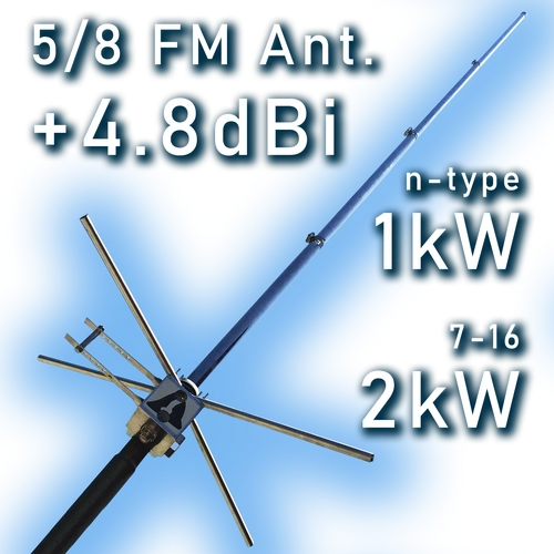
5/8 Wave 2KW Vertical High Gain FM Broadcasting Antenna
- 4.8dBi Gain (x3 TRANSMITTER POWER)
- SUPER 2kW HIGH POWER CAPABILITY
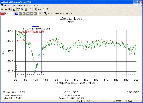
- VSWR ≤ 1.5 FROM 87.5 TO 108 MHz
- TRUE 360° OMNI-DIRECTIONAL
- AVAILABLE WITH DIN 7-16 CONNECTOR
- LIGHTWEIGHT AT UNDER 2Kg
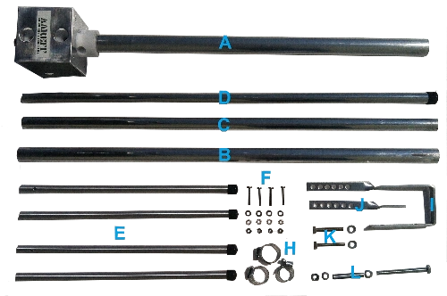
- EASY ASSEMBLING FOR NOVICES
- EASY INSTALLATION
- PRICE INCLUDES SHIPPING


High-Power Engineering: 2kW+ Sustained Performance
Industrial-Grade Thermal Management & RF Efficiency: Aareff’s high-power antenna design eliminates the common failure points found in standard broadcast equipment. By removing traditional coils and capacitors, we have engineered a system that manages extreme RF energy without the risk of overheating or component degradation.
| Technical Superiority | Aareff Engineering Standard |
|---|---|
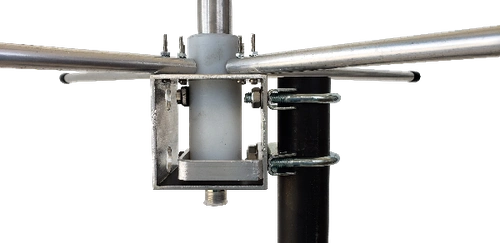
| Solid Aluminum Transformation | Instead of fragile components, we use solid aluminum tuning bars and a precision-engineered base to transform the unbalanced 50-ohm feed to approximately 1000 ohms. This robust construction ensures that even at 2kW continuous power, the antenna remains cool to the touch. |
| Premium Teflon Insulation | Our primary insulator is high-grade Teflon, which is virtually transparent to the RF signal. This prevents heat absorption and maintains pristine signal integrity at high voltages. |
| 3kW Capability Ceiling | While rated for 2kW, the physical architecture of this antenna is capable of handling up to 3kW. The only limiting factor is the 7-16 DIN connector itself, not the antenna’s structural or electrical design. |
Advanced Low-Loss Insulators: UHMW PE & Teflon Technology
Superior Dielectric Strength & Wind Resilience
Aareff antennas utilize UHMW PE (Ultra High Molecular Weight Polyethylene) insulators to ensure peak performance in the most demanding climates. While Teflon is a standard in RF engineering, our use of UHMW PE provides a strategic advantage for outdoor broadcast installations.
• Extreme Dielectric Strength: With a dielectric strength of 28kV/mm, UHMW PE provides incredible insulation, ensuring that high-voltage RF energy remains focused on transmission rather than being lost to heat.
• 5x Stronger than Teflon: In high-wind environments, physical structural integrity is paramount. UHMW PE is five times stronger than standard Teflon, allowing the antenna to maintain its 2-meter physical geometry even during severe storms.
• Optimized Coaxial Efficiency: At the 88-108 MHz FM band, line losses can degrade signal quality. To maintain the 4.8dB gain of the 5/8 wave design, we recommend high-quality coaxial cables such as LMR400 or equivalent for all long-run installations.
Proven Reliability & Long-Term Performance
Proven Engineering & Field Reliability
Since its original design in 1996, Aareff has deployed over 1,000 of these 5/8 wave antennas worldwide with a near-zero return rate. This system represents peak Experience in RF engineering, offering high power handling and a gain of approximately 4.8dB—effectively increasing your radiated power by 2.8 times.
Owing to its high-gain performance and rugged construction, this model has become a highly popular antenna in The Netherlands, serving as a trusted choice for Dutch broadcasters who require consistent, long-range signal penetration.
Build Quality & Durability:
• All-Weather Resilience: Designed to operate in rain and moderate snow, featuring high-grade physical strength for long-term outdoor exposure.
• Low Maintenance: Proven field performance with customers reporting over 15 years of continuous service with little to no maintenance.
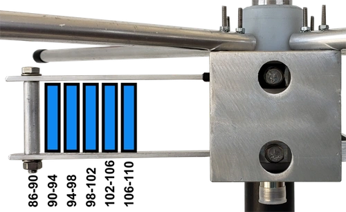
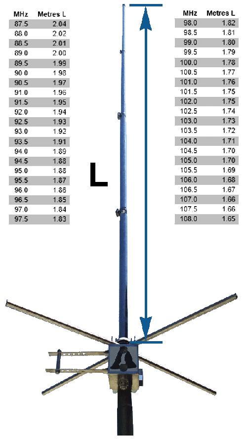
• Precision Tuning: Every antenna is precisely tuned to your specific operating frequency to ensure a perfect impedance match for your transmitter.
Advanced Interference Suppression & Signal Efficiency
Engineered for Low EMI & TV Interference
Aareff’s 5/8 wave antenna is meticulously engineered to minimize electromagnetic interference (EMI) in sensitive environments. Unlike a standard dipole, our design ensures that with correct mounting, the RF field strength directly below the antenna is significantly reduced.
Technical Advantages for Clean Broadcasting:
• True Unbalanced Input: This critical design feature prevents stray RF currents from traveling down the outer shield of the feeder cable, protecting your equipment and nearby electronics.
• Tight Bandwidth Optimization: By maintaining a narrow, precision-tuned bandwidth, the antenna considerably reduces the risk of audio, TV, and other local signal interference.
• Maximum Horizon Power: This specialized configuration doesn't just reduce interference; it maximizes the concentration of RF power toward the horizon, ensuring your signal reaches your audience with peak efficiency.
| Gain (Isotropic) | +4.8 dBi |
| Frequency Range | 87 - 109 MHz |
| Bandwidth | +/-2 MHz 1.5 VSWR |
| Construction | UHMW PE/Aluminum |
| RF Connectors | N type / DIN 7-16 |
| Impedance | 50 ohm unbalanced |
| Polarization | Vertical |
| Maximum RF Power | 1kW / 2kW |
| Weight of Antenna | 1.8Kg |
| Wind Speed Handling | 90 MPH |
Do you want cable for your antenna?
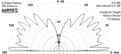
Radiation Pattern
The Aareff 5/8 wave antenna is engineered to provide a perfectly circular radiation pattern when viewed from above at the 0-degree point. This horizontal symmetry ensures uniform signal distribution across your entire broadcast area. By concentrating the signal cross-section between the antenna and the horizon (at 0 and 180 degrees), this geometry minimizes wasted sky-ward energy and maximizes effective range.
See the radiation pattern diagram below:


 IMPORTANT!