 +1 829 698 0733
What Do You Need? Talk To Us
+1 829 698 0733
What Do You Need? Talk To Us8am-4pm EST/NY Monday-Friday info@aareff.com

User Manual and Installation of 1/2 Wave Double Colinear Antenna (Mamasita)
SAFETY TO PERSONNEL
 IMPORTANT!
The antenna is the most important part of the transmission system and must be correctly installed before proceeding further and before any transmission equipment is connected.
Under no circumstances should the antenna be mounted and used at ground level or within a few meters of personnel.
Ideally this antenna should be mounted at least 20 meters high and clear of any surrounding objects to get maximum range and more importantly to reduce risk of radio frequency radiation to personnel. When mounted at least 20 meters in height off ground and using 1000 watts of transmitter power, power flux density measurements made at ground level directly under the antenna show less than 1 W/m2. Several European countries use a value for the power flux density of 10 W/m2 as a basis for considering whether or not an area is safe. The issue of radio frequency radiation limits is a contentious one and work in this field is continuing worldwide.
You are responsible for selecting the correct antenna for your application, installing it properly and ensuring the system maintenance.
INTENDED USE
This antenna is intended for use with an FM broadcasting transmitter up to 1kW for N-type connector or 3kW for DIN 7-16 connector at a permanently pre-defined location with a license or authorisation from the radio spectrum regulator of your country.
TO ERECT THIS ANTENNA YOU WILL NEED TO PROVIDE
| PVC Insulation Tape and Self Amalgamating Tape |
| 13mm Spanner or Socket and Wrench (For the U clamps D) |
| 10mm Socket and Wrench (Used to fasten the Phasing Stub (A) onto the PTFE Phasing Stub Insulator (J) in between the two Radiator Tubes (L/K) and to clamp |
| the Tuning Bar (F) / Tuning loop (E) to the Base Section (B). |
| 7mm Spanner or Socket and Wrench (Used to fasten the Ground Plane Tubes (C) to the Base Section (B)) |
| Philips Screwdriver (Used to fasten the Ground Plane Tubes (C) to the Base Section (B)) |
| Mounting Mast or Pole with a diameter of 65mm |
| Antenna 50 ohm Feeder Cable. For example LMR400 |
INSTALLATION NEAR TO POWER LINES
Following is a list of precautions to follow when installing the antenna if placement of antenna and cables is anywhere near power lines.
| Erect antenna on side of house or building as far away as possible from the power line. |
| Avoid crossing antenna cables under electrical power lines. |
| Do not attach antennas to towers, poles or similar structures carrying electrical power lines. |
| If you are not experienced in installation of antennas, have experienced persons assist you. |
| During installation, tie off antenna with rope so if it falls it can be diverted away from power lines. |
| Avoid fastening antennas, especially self-supporting types, to old chimneys or to any chimney not designed to take such stress. Forces created by a strong wind may be sufficient to topple both chimney and antenna. |
| Make sure antennas have been properly grounded and provided with other necessary lightning protection. |
PACKAGE CHECKLIST
| Qty | Item |
| 1 | A Phasing Stub |
| 1 | B Base Section With Teflon Insulator And RF Socket |
| 4 | C Ground plane tubes 1/2” |
| 2 | D Mast Fixing Clamps |
| 1 | E Tuning Loop |
| 1 | F Tuning Bar |
| 1 | G Tuning Loop Screw Sleeve Nut and Washer |
| 4 | H M6 Phasing Stub Tuning Loop and Tuning Bar Screws and Washers |
| 8 | I M4 Ground Plane Screws Nuts And Washers |
| 1 | J Center Phasing Stub Teflon Insulator |
| 1 | K Main bottom radiator tube |
| 1 | L Main top radiator tube |


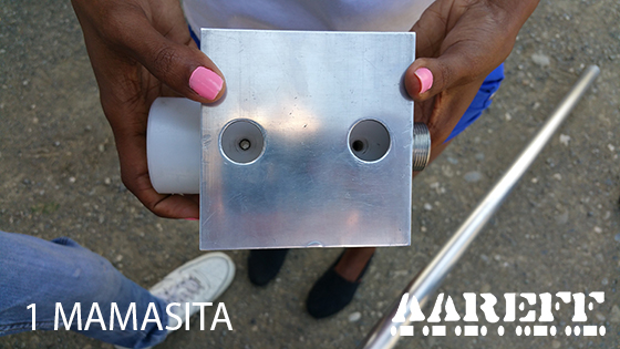
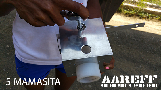
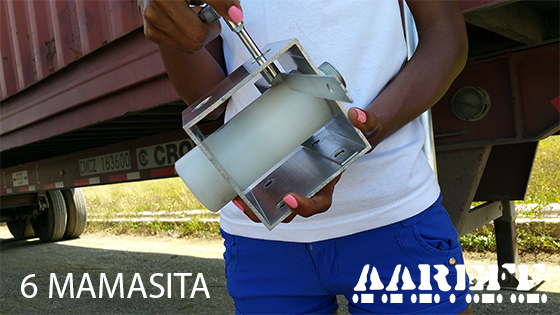
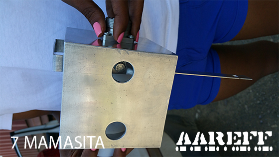
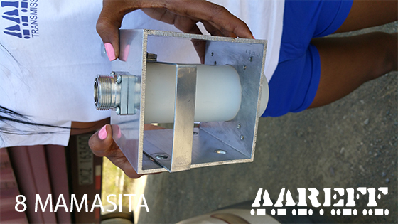
ASSEMBLING THE BASE SECTION AND THE TUNING LOOP
Using one of the (H) M6 Screws and Washers and the 10mm Socket and Wrench, fit the (E) Tuning Loop to the (B) Base Section as shown in photos 1 to 8 below. Make sure the screw is tight.
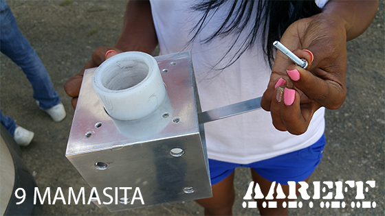
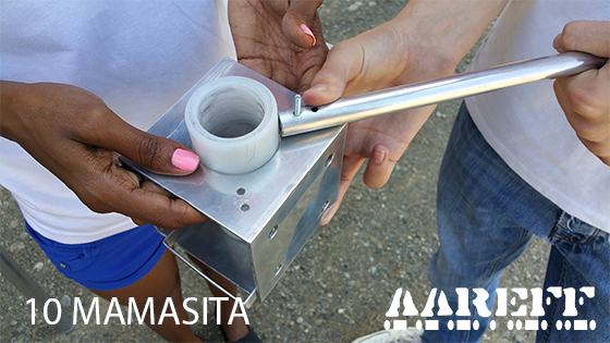
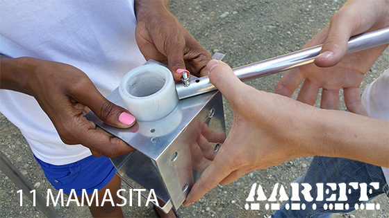
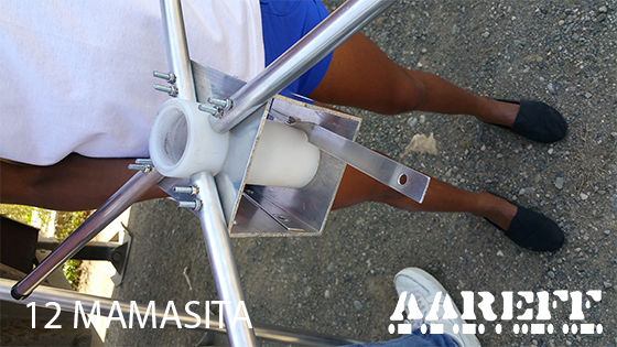
ASSEMBLING THE BASE SECTION AND THE GROUND PLANE TUBES
Using the eight (I) M4 Screws, Nuts and Washers, Philips Screwdriver and the 7mm Spanner or Socket and Wrench, fit the four (C) Ground Plane Tubes to the Base Section as shown in photos 9 to 12 below.
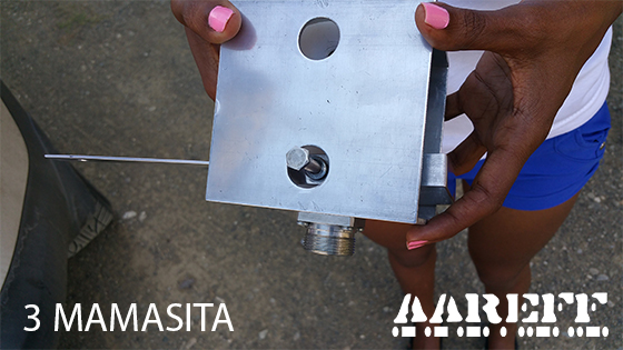
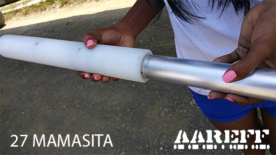
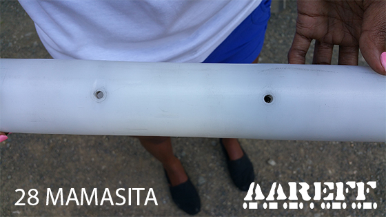
ASSEMBLING THE BASE SECTION AND THE BOTTOM MAIN RADIATOR TUBE
Take the (K) Bottom Main Radiator Tube, this is the long aluminium tube with a brass insert and holes for screws in both ends, be careful not to confuse it with the top main radiator tube. Insert the Bottom Main Radiator Tube into the base section. This should be a tight fit and you may need to have a little patience and perseverance to get it into the hole correctly. Follow photos 13 to 16 below. The hole in the PTFE insulator in the Base section should line up with the hole in the brass insert of the Bottom Main Radiator Tube. When it is inserted and lined up correctly it should be easy to enter one of the (H) M6 Screws and Washers as shown in photo 16. At this point only try the M6 Screw in the hole to see if it fits okay, then take it back out.
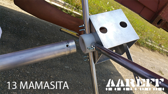
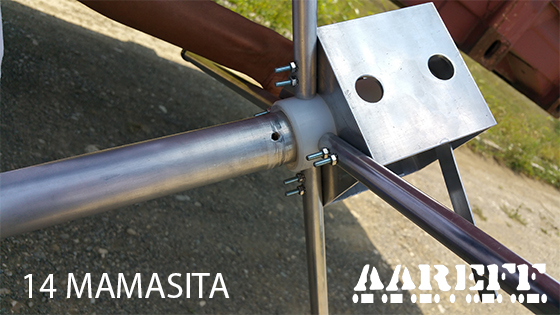
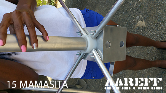
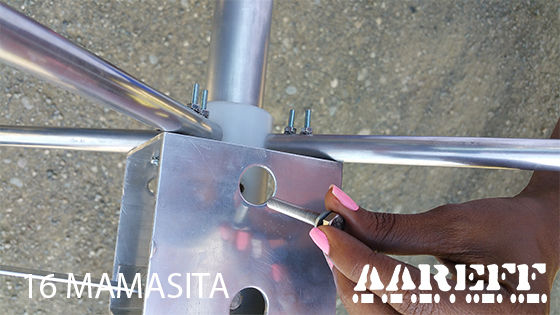
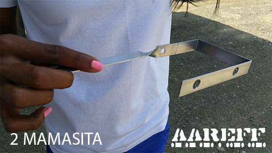
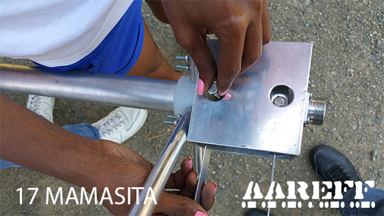
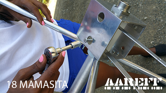
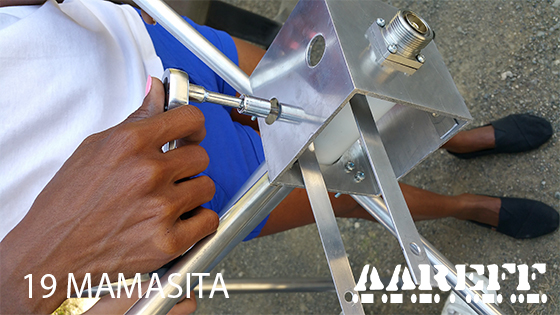
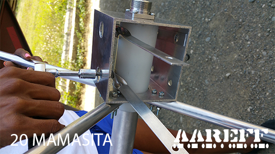
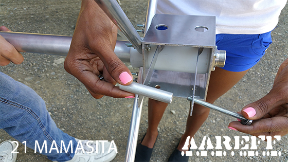
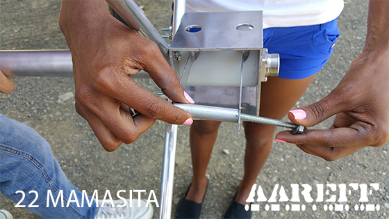
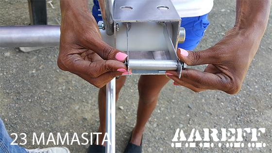
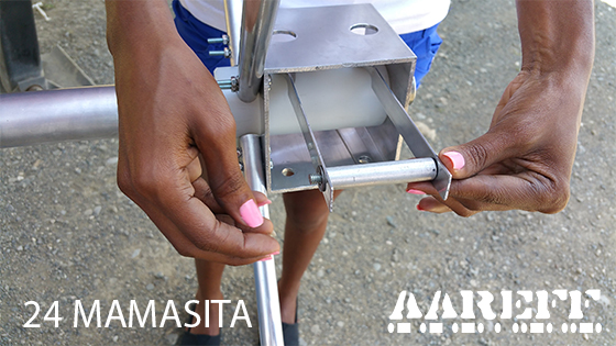
ASSEMBLING THE BASE SECTION AND THE TUNING BAR
Using one of the (H) M6 Screws and Washers and the 10mm Socket and Wrench, fit the (F) Tuning Bar to the (B) Base Section as shown in photos 17 to 20 below. Make sure the screw is tight holding the Tuning Bar and the Bottom Main Radiator Tube securely.
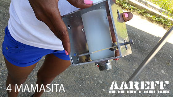
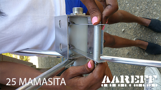
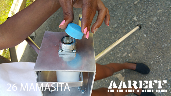
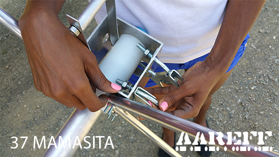
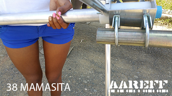
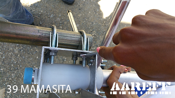
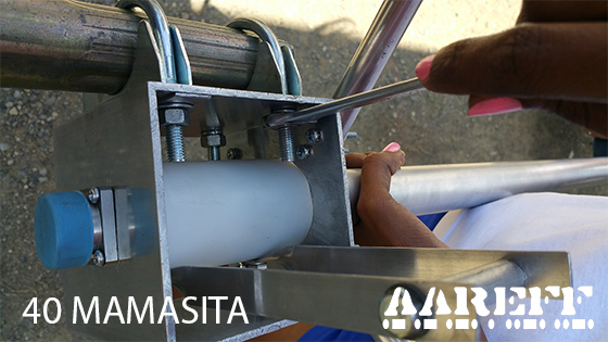
ASSEMBLING THE TUNING LOOP AND THE TUNING BAR
Using (G) Tuning Loop Screw, Sleeve, Nut and Washer and the 10mm Socket and Wrench fit the aluminium sleeve between the Tuning Bar and the Tuning Loop as shown in photos 21 to 26 below. The nut should be really tight up against the star washer, this will prevent it shaking loose in the wind. Take care to make this connection good, when operational it carries a huge amount of power. Please make sure the plastic protective cover is over the RF socket.
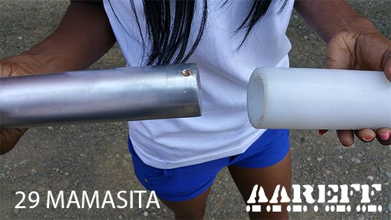
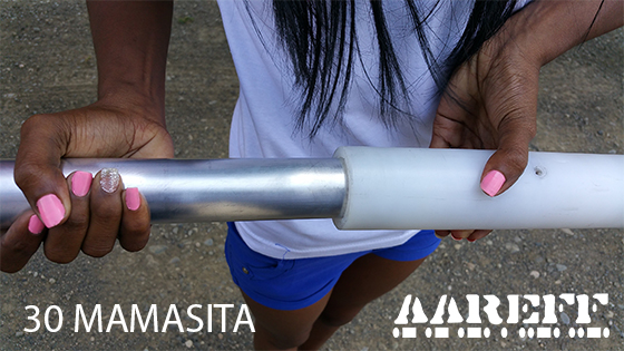
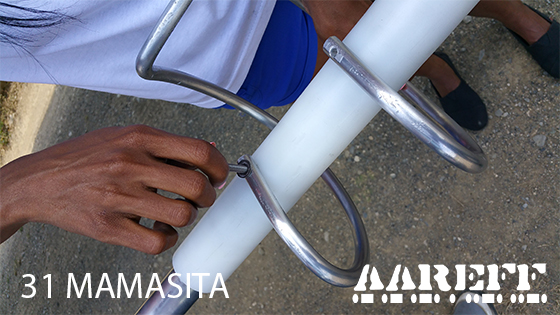
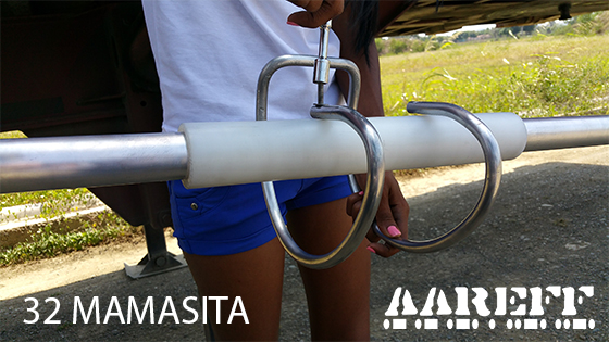
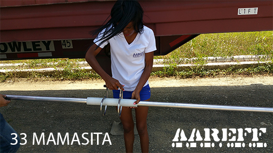
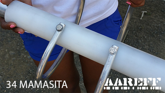
ASSEMBLING THE MAIN RADIATOR TUBES AND THE PHASING STUB
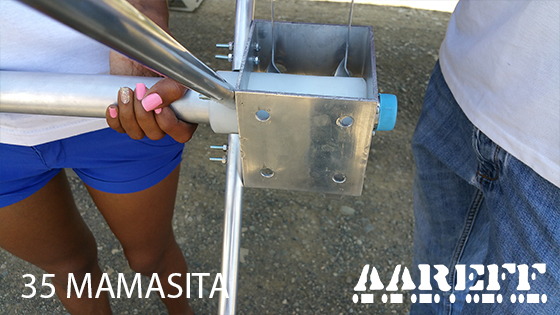
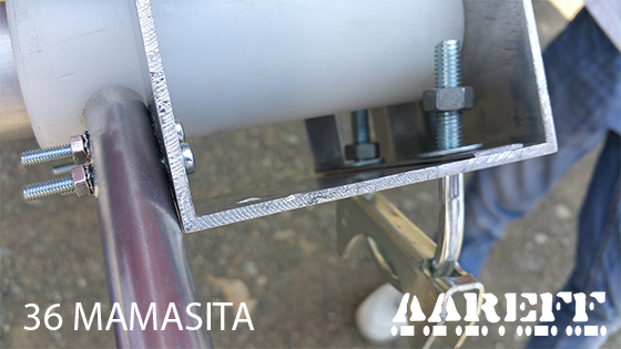
ASSEMBLING THE MAST FIXING CLAMPS AND THE BASE SECTION
CONNECTING THE ANTENNA
IMPORTANT!
An incorrect antenna installation can cause RF burns and levels of RF exposure above the recommended limits for personnel
Under NO CIRCUMSTANCES should the antenna be mounted and used at ground level or within a few meters of personnel
Ensure that all antenna connections to the transmitter or power amplifier are sound, this is important as poor connections and soldered joints can cause RF burns to personnel, severe noise to the transmission and excessive RF bandwidth.
ANY QUESTIONS?
EM COMPATIBILITY
When writing this manual there was no EU directive regarding the EMC (Electro Magnetic Compatibility) of Band II VHF broadcast antennas, however in our view there are some potential EMC compatibility issues that need to be addressed when installing this antenna system. On completion of the antenna installation check;
- All the cables entering the connectors are tight and properly crimped or soldered
- All the connectors are screwed in tight and sound.
- PVC insulation tape and/or self amalgamating tape are wrapped around all the connectors to stop water entering the connector and the inside of the body of the cable.
If any cables are loose or there are bad connections this can cause some non-linear resistance, diode action or some small arcing. When this happens it creates EMC disturbance (arcing and crackling sound) across a wide frequency spectrum.
TECHNICAL SPECIFICATION
| Antenna Gain (Isotropic) | +6.7 dBi |
| Frequency Range | Tuned at Factory between 97.5 and 108 MHz |
| Bandwidth | +/-4 MHz for SWR of 1.5 SWR 1.1 Max at tuned frequency |
| Construction | Aluminium and Teflon |
| RF Connectors | N type or DIN 7-16 |
| Impedance | 50 ohm (1.1 SWR) unbalanced input |
| Polarisation | Vertical |
| Maximum RF Power | 1kW or 3kW |
| Weight of Antenna | 6 Kg |
| Wind Speed Handling | 90 MPH Minimum |
MAINTENANCE
Because antennas are passive devices maintenance requirements are low, however don’t accept low as being none existent, some periodic inspections are required.
Antenna Inspection List;
- Check antenna is still rigid and tight on tower, mast or pole and vertical tubes are still exactly vertical as opposed to twisted and slanted.
- The PVC tape insulation or self amalgamating tape still covers all the connectors properly and the connectors remain tight.
- The antenna feeder cable (normally LMR400) continues to be held rigid to the boom, tower, mast or pole.
Always following a heavy storm or extreme weather condition an inspection should be done and as shown in the table below.
| WEEKS | Building Roof | Light Duty Tower | Heavy Duty Tower |
| 13 |  |
||
| 26 | |
|
|
| 39 | |
||
| 52 | |
|
|
LEGAL ADVICE
We sell this equipment to professionals and organizations in good faith it will be used correctly and legally. Most countries in the world require licensing for this antenna to be used with a transmitter. It is the customer’s responsibility to check relevant laws, directives, regulations and licensing requirements before putting this product into service with an antenna system. You, the customer or user agree to defend, indemnify and hold harmless Aareff Systems Limited, its employees and agents, from and against any claims, actions or demands, including without limitation legal and accounting fees, alleging or resulting from improper or unlawful use of this equipment.
© 2019 AAREFF SYSTEMS LIMITED
ALL RIGHTS RESERVED. Aareff is a trademark of Aareff Transmission Systems. All contents of this document including, but not limited to the images, logos, text, illustrations are protected by copyrights, trademarks and other intellectual property rights which are owned and controlled by Aareff Transmission Systems or by other parties that have licensed their material to Aareff Transmission Systems. This document in part or whole may not be copied, reproduced, republished, uploaded, posted or distributed in any way, including by e-mail, ftp or any other electronic means
Every care has been taken in the preparation of this document, errors in content, typographical or otherwise, may have occurred. If you have comments concerning its accuracy, please contact Aareff Systems Limited (UK)


