 +1 829 698 0733
What Do You Need? Talk To Us
+1 829 698 0733
What Do You Need? Talk To Us8am-4pm EST/NY Monday-Friday info@aareff.com

User Manual - 10 Watt FM Radio Broadcasting Transmitter

INTENDED USE
i. The equipment in this document is only for use permanently at a pre-defined location with a license or authorisation from the radio spectrum regulator in your country or EU member state.
ii. The installer must have competent RF engineering skills at their disposal, be EMC aware and understand radio frequency systems. The final installation should be in accordance with the EU and the US techincal parameters and the maximum audio deviation level for the full composite MPX signal should be adjusted to b an absoulte maximum for +/-75 KHz.
USA REQUIREMENTS. Section 2.1047 Modulation characteristics and section 2.1049 Occupied bandwidth at:
http://www.gpo.gov/fdsys/granule/CFR-2011-title47-vol1/CFR-2011-title47-vol1-sec2-1047/content-detail.html
EU REQUIREMENTS. Section 8 Audio Processing Limiter at:
https://www.aareff.com/ETR132.pdf
PACKAGE CHECKLIST
| Qty | Description | Item |
| 1 | 10W FM Transmitter | |
| 1 | IEC AC Cable (AC VERSION ONLY) |  |
| 1 | DC Cable (12V DC VERSION ONLY) | 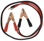 |
USA TECHNICAL REQUIREMENTS
Some versions of this transmitter do not include internal audio limiting. To maintain compliance with the FCC rules and technical requirements the audio source / feed should be level controlled to prevent over deviation and excessive use of bandwidth by means of an external audio limiter and/or processing device, MPX stereo generator and/or RDS generator. More information on this is at is in section 2.1047 Modulation characteristics and section 2.1049 Occupied bandwidth at http://www.gpo.gov/fdsys/granule/CFR-2011-title47-vol1/CFR-2011-title47-vol1-sec2-1047/content-detail.html
EU REGULATORY REQUIREMENTS
Some versions of this transmitter do not include internal audio limiting. To maintain compliance with the EU ETSI standard the audio source / feed should be level controlled to prevent over deviation and excessive use of bandwidth by means of an external audio limiter and/or processing device, MPX stereo generator and/or RDS generator. More information on this in section 8 Audio Processing Limiter at https://www.aareff.com/ETR132.pdf
This product complies with EMC directive of the European Union. To meet this directive the user or installer must follow the wiring instructions in the this user manual
This equipment is not intended for installation by an unqualified end user, the installer must have competent RF engineering skills and EMC knowledge at their disposal. The whole transmission system, including the antenna system and external audio limiting, should be installed in the EU in accordance with document ETR132, a copy of this is available at https://www.aareff.com/ETR132.pdf
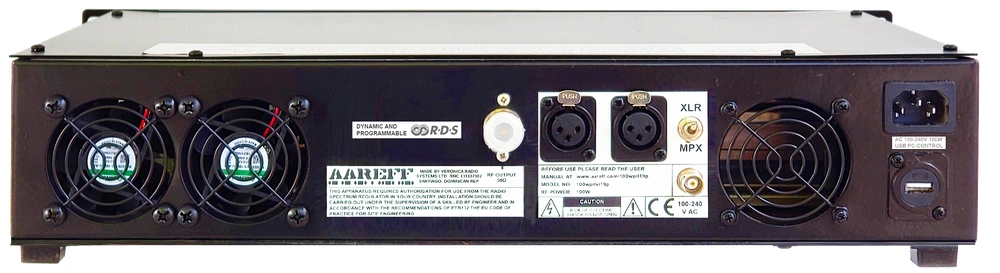
CONNECT THE ANTENNA TO THE RF OUTPUT
 The ANTENNA is very important, check this is installed and ready to use. DO NOT EVER POWER A TRANSMITTER OR RF AMPLIFER WITHOUT AN ANTENNA CONNECTED.
PLUG THE ANTENNA CABLE INTO THE TRANSMITTER. Make sure this tight as poor and loose connections can cause RF burns to personnel, severe noise to the transmission and excessive RF bandwidth. A transmitter should never be operated without an antenna. DO NOT PLUG IN THE POWER CORD AT THIS STAGE.
Under NO CIRCUMSTANCES should the antenna be mounted and used at ground level or within a few meters of personnel.
A tuned antenna with the 50 ohm coaxial cable should be used. This should give a return loss ideally of 16dB (SWR 1.4) or better at the operating frequency. The RF plug should be PL259 (UHF) or N type, depending which is fitted to the FM transmitter.
Ensure that all antenna connections are sound, this is important as poor connections and soldered joints can cause RF burns to personnel, severe noise to the transmission and excessive RF bandwidth. Do NOT connect the antenna to the transmitter yet.
Ideally the antenna for this transmitter should be ideally mounted 20 meters high and clear of any surrounding objects to get maximum range and more importantly to reduce risk of radio frequency radiation to personnel. When mounted at 20 meters in height off ground and using 10 watts of transmitter power, power flux density measurements made at ground level directly under the antennas described above show less than 1 W/m2. Several European countries use a value for the power flux density of 10 W/m2 as a basis for considering whether or not an area is safe. The issue of radio frequency radiation limits is a contentious one and work in this field is continuing worldwide.

BOTTOM PANEL CONTROLS
Turn the transmitter upside down to locate the following controls:
If you have the latest model, then you will have the following components:
- VR2 - RF Power Output Control
- Two Small Buttons for Stepping Freq Up and Down.
- VR1 - FM Deviation Control
BE CAREFUL not to be too heavy handed, these controls are only small pcb mounted pots and switches and can be damaged with excessive force. You will need to use a small electrical screwdriver to adjust these controls.
SET THE RF POWER OUTPUT TO ZERO
If you are connected directly to an antenna, as a safety precaution adjust VR2 RF PWR. ADJ fully counter-clockwise. In this counter-clockwise position the transmitter output will have no RF output, it is reduced to zero. IMPORTANT! This is to prevent interference to the radio spectrum if you are not on the correct frequency or not set up properly.
POWERING THE TRANSMITTER
Double check the power is reduced to zero as described in the section above SET THE RF POWER OUTPUT TO ZERO and connect AC or DC power cord as shown below
◼ AC VERSION
A standard IEC AC power cord is supplied for connection to any AC between 90 and 260 volts.
◼ DC VERSION. Be careful, please read !!!
A DC power cable is supplied rated at 5 amps for 12V DC operation. Please BE CAREFUL to connect to the 12V battery with the correct polarity. RED to + and BLACK to -. Make sure the connection is solid, not intermittent or loose. A loose connection causing the unit to stop and start randomly and rapidly can damage the internal regulators. Connection is normally directly to the vehicle battery or other 5 amp source.
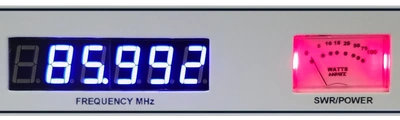
Once the power cord is connected you should hear the cooling fans start up. Observe the front panel Power Meter. The Power Meter should show zero. If it is not zero, disconnect the power cord immediately and double check the power is reduced to minimum as described in the section above SET THE RF POWER OUTPUT TO ZERO.
The Power Meter should light up RED, this may change to BLUE after a few seconds, if it does great, if it doesn't, don't worry at this point, this is also normal.
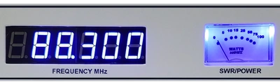
SET THE FREQUENCY
Locate the two small frequency up and down buttons. These small buttons are used for stepping up or down in selecting a frequency. As you press the up or down buttons, you'll notice the frequency on the digital display change. It's important to select your frequency correctly, if you don't, it's possible to transmit on an unauthorised frequency.
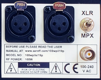
CONNECTING THE AUDIO BASEBAND
Stereo Version The stereo version use standard XLR balanced input (+4dBu nom.) and also has the option for direct MPX input. This is self explanatory how it works. Switch UP for XLR stereo input and switch DOWN for direct MPX input. In the MPX mode, the RDS internally continues to function and is mixed with the incoming MPX signal. If the incoming MPX contains RDS from another source, then internal RDS can be turned off permanently via the USB PC control.
MPX Version The MPX version is exactly the same as stereo version, the only difference being that the XLR connectors and switch are omitted and there is no RDS as standard. RDS can easily be fitted as an option, contact us if this interests you.
CHECKING THE AUDIO DEVIATION
During manufacture and test the audio deviation will be set broadcast standard line of +8dBu peak for +/-75KHz peak deviation at 88.0 MHz. There is a high possibility that this will not be the same level as the audio source feed from your studio, external audio limiter and/or processing device, MPX stereo generator and/or RDS generator. You need to check this as excessive deviation can cause adjacent channel interference to other users of the radio spectrum.
WITHOUT TEST EQUIPMENT
Audio deviation is difficult to measure without proper test equipment and the method described here cannot replace proper test equipment, however if your regulator permits this method it is possible to check the deviation very close to correct level by using a relative comparison. Use a radio receiver tuned to a known high quality, high budget and reputed radio station. For example in the United Kingdom this would be a national BBC station. Feed the audio output of the radio receiver into some VU meter or level indication on a mixer or other audio equipment. Look carefully at the metering level peaks. You will notice the meter peak constantly at a specific level, make a note of this. Place the antenna of radio receiver as close as possible to your transmitter enclosure. Re-tune the radio receiver to your transmitter frequency. Look at the metering again. Adjust VR1 DEV. ADJ. so that your audio constantly peaks at a little lower than the level you noted. When you have achieved this your deviation is a little lower or close to the legal level. The reason for this setting is that it is legal to under deviate, but not-legal to over deviate, with a lack of test equipment
It is better to be under deviating in order to prevent adjacent channel interference until you have proper test equipment available.
WITH TEST EQUIPMENT
Connect the transmitter via a coupler and dummy load to a Spectrum Analyzer, Modulation Analyzer or Deviation Meter. Adjust VR2 RF PWR. ADJ fully ANTI-clockwise. Adjust VR1 DEV. ADJ. for the correct deviation on the test equipment.
SET THE RF POWER OUTPUT LEVEL
Locate the power control VR2 RF PWR. ADJ. If you followed the previous paragraphs, this power control should be in the counter-clockwise. In the fully clockwise position the transmitter output is at maximum RF output. Check the switch on the front panel is set to FWD. Adjust this control to the desired power level. THE TRANSMITTER IS NOW ON AIR!
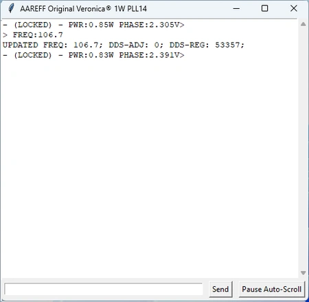
USB PC/RDS CONTROL
Download our free PC app that connects 'plug and play' to the transmitter / PLL DDS exciter via USB. You can see the PLL status and change the frequency and power directly from the PC interface. If you choose to add the optional RDS card, you can also change the PI, PTY and scrolling text of the radio from the interface.
Below are the download links for Windows:
https://www.aareff.com/1wpllm/pll14.4/pll14.exe
https://www.aareff.com/1wpllm/pll14.4/pll14.zip
By clicking on these links, Windows may show you a warning that the software is from an unknown publisher. We assure you that we wrote the apps and the files are perfectly safe, virus-free and come from our registered domain www.aareff.com, which you can verify at https://lookup.icann.org/en/lookup
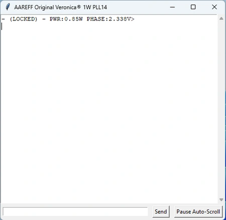
Normal state when the device is connected: the PLL is LOCKED with an output power of 0.85W and a PLL phase of 2.33V
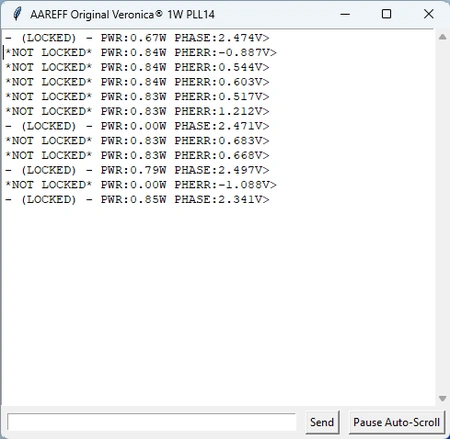
This shows what happens if the device loses its lock. We simulated a failure by placing our fingers on the oscillator coils.
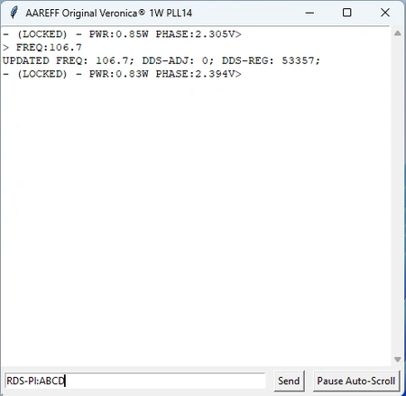
This shows the return to normal with the user command FREQ:106.7 typed in the input box below. A value between 87.5 and 108.0 MHz can be set.
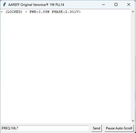
After pressing 'Send:' the display returns UPDATED FREQ 106.7 along with other technical information. This causes the transmitter to change frequency.
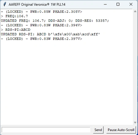
This shows another command, RDS-PI:ABCD typed for devices with the RDS card.
After pressing 'Send': the display returns UPDATED RDS-PI:ABCD instantly updating the RDS PI code.
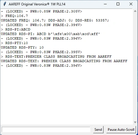
This shows two additional examples of RDS commands:
RDS-TEXT:[write your message here]
RDS-PTY:[number from 0 to 31]
Text is plain ASCII up to 60 chars and valid PTY Codes shown below.
Shown below are the current commands available for USB PC Control and also the PTY codes for program type. We will be making further developments, improvements and more useful commands to this app in the near future. Keep checking this page for details.
◼ DEVICE-ID
◼ STATUS
◼ FREQ:[87.5 to 108.0]
◼ DDS-ADJ:[-1,0 or 1]
◼ PWR:[0 to 1]
◼ RDS-PTY: [0 to 31 list of PTY codes]
◼ RDS-PI: [0000 to FFFF]
◼ RDS-TEXT:[any string up to 60 chars.]
◼ RDS-ON
◼ RDS-OFF
NORMAL OPERATION
On units with fans fitted should hear the cooling fan. The fan draws air into the front and exits the warm air through the rear vents. It is important to keep these vents clear. The front meter should illuminate in BLUE
The front panel meter should show 10 watts. If the transmitter power is set to full but you are only seeing 15 to 20% of the power on the meter, it is almost certain, 99% certain, you have a serious antenna problem such as shorted wires or broken wires in the coaxial cable connector or the antenna is incorrectly assembled. This is normal and it is the transmitter reducing the power automatically to protect itself from permanent damage. If you resolve the connector, shorted or broken wires or antenna assembly, the the power will return to 100%.
TECHNICAL DATA
(All stated measurements were made at 220VAC at 26 Degrees Celsius ambient temperature unless stated)
RF and AF Parameters
| Power Output Adj. | 1-10 Watts into 50 ohms |
| Freq Range | 87.5 to 108 MHz |
| Spurious Emissions | Less than -75 dB ref to carrier |
| Harmonic Emissions | Less than -70 dB ref to carrier |
| Out of Lock RF Muting | Less than -70 dB ref to carrier |
| Freq Stability | Less than +/- 2 KHz between -20 and +40 C |
| Freq Fine | Adj +/- 1000 Hz |
| Freq Adj. Accuracy | +/- 50 Hz |
| Deviation Sensitivity Stability | +/-2 % max |
| Residual AM | Less than 0.5 % |
| Synchronous AM | Less than 0.5 % |
| RF Output Connector | N-Female |
| RF Ruggedness | Any VSWR, phase, length of time |
| MPX Audio Input | Connector Phono/ RCA type unbalanced |
| Pre-emphasis | (50uS/ 75uS/ None) |
| MPX Audio Input Sensitivity | Nom. 0.775 V rms for +/- 75 KHz Dev. User adj. |
| MPX Signal To Noise Ratio | More than 72 dB rel. +/-75KHz dev. |
| MPX Audio Freq Response | Less than +/-0.5dB between 30 Hz and 76 KHz |
| MPX Audio Distortion | Less than 0.2 % THD |
| Operating Temp | -20 to +40 Deg C |
AC Mains Parameters
| Input Voltage | 100-120VAC or 200-240VAC 47-63Hz Check Rear Panel Label |
| Input Power | 28 for 10W RF OUT with RF SWR less than 1.5 |
| Power Factor | PF>0.95/230VAC PF>0.98/115VAC at full power |
| Working Humidity | 20 ~ 90% RH non-condensing |
| Safety Standards | UL60950-1, TUV EN60950-1 Approved |
| EMC Conduction & Radiation | Compliance to EN55022 (CISPR22) Class B |
| EMC Harmonic Current | Compliance to EN61000-3-2,-3 |
| EMC Immunity | Compliance to EN61000-4-2,3,4,5,6,8,11; ENV50204, Light industry level, criteria A |
MAINTENANCE
The only maintenance the amplifier needs is some periodic cleaning. Following a number of weeks of continuous 24/7 use (specified below), the amplifier should be shut down and disconnected. A technician or engineer needs to take of the top lid by removing the self tapper screws. Using a soft new and clean paint brush with a vacuum clean hose, the dust should be gently brushed and sucked away from all areas inside. Pay particular attention to the actual fans at the rear and the fan vent at front.
The table below shows the recommended number of weeks cleaning should be done for some typical environmental areas.
| WEEKS | SALTY | SANDY | DUSTY | PUBLIC | CLEAN |
| 4 |  |
||||
| 6 | |
|
|||
| 8 | |
||||
| 12 | |
 Do not adjust any factory set internal controls.
Under NO CIRCUMSTANCES should any adjustments be made to the internal controls. Such adjustments could damage the unit and invalidate the warranty and also cause serious interference to other users of the electromagnetic spectrum.
LEGAL ADVICE
We sell this equipment to professionals and organizations in good faith it will be used correctly and legally. Nearly every country in the world require licensing for this type of equipment. It is the customer's responsibility to check relevant laws, directives, regulations and licensing requirements before installing or putting this product into service with an antenna system. You, the customer or user agree to defend, indemnify and hold harmless Aareff Systems Limited, it's employees and agents, from and against any claims, actions or demands, including without limitation legal and accounting fees, alleging or resulting from improper or unlawful use of this equipment.
DECLARATION OF CONFORMITY
European Union
We hereby declare that this equipment complies with;
• ETS 300384 European Telecommunications Harmonised Standard when used with an audio compressor limiter supplied and tested by Aareff
• EN 301489-11 V1.3.1 (2006-05) EMC Electromagnetic Compatibility when used with 1 meter AC mains cord supplied. If the installation engineer needs to extend this cord, this and the audio input cable should be no more than 3 meters in length to remain in compliance with EMC directive.
• 2006/95/EC Directive (2006-12) LVD Low Voltage Directive.
Equipment compliance is possible using equipment from and in conjunction from other manufacturers, but since this is beyond the control of Aareff Systems, Aareff Systems cannot or be expected to guarantee compliance in this situation.
United States
The following list are the FCC technical requirements for FM broadcasting. We confirm and verify that this transmitter complies with the technical requirements.
47 CFR Chapter I Federal Communications Commission sections:
• 73.1560, 2.1046 RF Power
• 73.1545, 2.1055 Frequency Stability
• 73.317, 2.1049 (e)(3) Emission Limitation, Emission Mask
• 73.317, 2.1057, 2.1051 Emission Limits, Spurious Emissions at Antenna Terminal
• 73.317, 2.1057, 2.1053 Emission Limits, Field Strength of Spurious Emissions
ROHS
All components used in this apparatus are RoHS compliant and do not contain above the specified limits in any of the following restricted substances:
- Lead
- Hexavalent Chromium
- Mercury
- Cadmium
- Polybrominated Biphenyls (PBB's)
- Polybrominated Diphenylethers (PBDE's)
PRODUCT END OF LIFE
This apparatus must NOT be disposed of with other domestic waste.
We are fully committed to maintaining our responsibilities to the environment. Owners of apparatus that has reached the end of it's useful life can return it to us for recycling, recondition, reuse or proper disposal. You will be required to pay lowest cost postal service available to ship the apparatus to us. Before shipping please contact us for more important information.
NEED TO BUY ONE?
© 2023 AAREFF SYSTEMS LIMITED
ALL RIGHTS RESERVED. Aareff is a trademark of Aareff Transmission Systems. All contents of this document including, but not limited to the images, logos, text, illustrations are protected by copyrights, trademarks and other intellectual property rights which are owned and controlled by Aareff Transmission Systems or by other parties that have licensed their material to Aareff Transmission Systems. This document in part or whole may not be copied, reproduced, republished, uploaded, posted or distributed in any way, including by e-mail, ftp or any other electronic means
Every care has been taken in the preparation of this document, errors in content, typographical or otherwise, may have occurred. If you have comments concerning its accuracy, please contact Aareff Systems Limited (UK)


