What does Motorola say about vertical antenna isolation?
Motorola's Standards and Guidelines for Communication Sites (R56, 2005), Section 8.4.1, gives a widely cited practical guideline for vertically separated transmitting and receiving antennas:
| Clear vertical separation | Illustrative antenna isolation |
|---|---|
| 3 metres (10 feet) | 45 dB |
| 6 metres (20 feet) | 55 dB |
Motorola specifies the clearance from the tip of the lower antenna to the base of the upper antenna. These figures refer to antenna-to-antenna isolation, not merely the loss calculated from distance in free space. They are useful planning guidelines, not a guaranteed isolation specification for every combination of frequencies and antenna models.
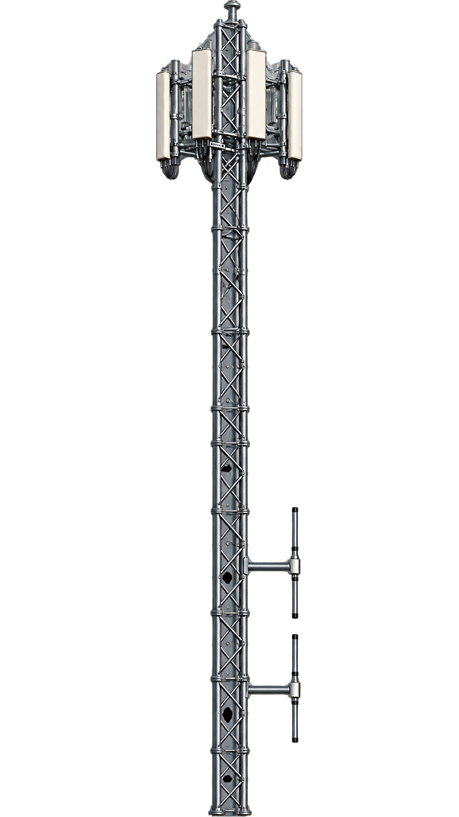
In the example shown here, the cellular panels are positioned approximately six metres above the uppermost FM dipole. This provides a convenient starting point for evaluating coexistence. Read Motorola R56, Section 8.4.1, page 8-9 (PDF).
Why can a two-bay FM dipole array help?
A vertical half-wave FM dipole radiates most strongly outward toward the horizon and has a natural radiation null along its vertical axis. Two identical dipoles stacked approximately half a wavelength apart and fed in phase add an array-factor cancellation mechanism in the upward and downward directions.
At 100 MHz, the wavelength is approximately 3 metres. For a practical two-bay design, the dipole feedpoints may therefore be separated by about 1.5 metres; each physical dipole is roughly 1.4 metres long. The tips of adjacent dipoles consequently sit close together, with a small gap.
In an ideal far-field model, the individual dipole nulls and the in-phase, half-wave-spaced array factor produce very low radiation directly above the array. In real installations, the actual upward coupling is affected by the tower, mounting hardware, feed phases, cabling and the relatively short separation distance.
Practical implication: A correctly phased two-bay FM array can reduce upward radiation further than a single dipole under favourable conditions. But the additional isolation is not a fixed number of decibels and should not simply be added to Motorola's 55 dB guideline. The Motorola figure is already an antenna-to-antenna isolation estimate.
How do cellular antennas and receiver filters affect the FM signal?
Cellular panel antennas are designed for their allocated cellular frequency bands, whereas FM broadcasting operates between 87.5 and 108 MHz. The cellular panel's response at an FM frequency may be quite different from its advertised cellular-band gain or radiation pattern. Its actual FM-frequency rejection cannot be assumed without antenna data or measurement.
There is a second, distinct line of defence: the cellular receiver's RF front-end filtering. Band-selective filters, duplexers and other receiver components may attenuate the unwanted FM carrier before it reaches a sensitive amplifier or mixer. Motorola R56 specifically discusses receiver filtering to prevent desensitisation from nearby transmitters.
It is important to distinguish RF power coupled into the cellular antenna port from RF power remaining after receiver filtering. Filtering can reduce the latter, but it does not change the electromagnetic signal incident on the antenna.
Example: 500 W FM transmitter and six metres of separation
Consider a 500 W FM transmitter feeding a two-bay dipole array. Each dipole receives approximately 250 W, assuming an equal power split and ignoring feeder losses. We can illustrate the effect of nominal isolation by considering the transmitter as a whole:
| Item | Level |
|---|---|
| 500 W total RF transmitter power | +57 dBm |
| Assumed total antenna-to-antenna isolation, from Motorola's planning guideline | −55 dB |
| Illustrative power at the receiving antenna connection, if this isolation applies to the complete array | +2 dBm |
| Hypothetical additional FM-frequency rejection in the cellular receive path | −20 dB |
| Illustrative unwanted signal after that filter | −18 dBm |
This simplified budget is illustrative only. The actual array-to-panel coupling is not established by subtracting a guideline from transmitter power, and 20 dB of receiver filtering is an example, not a claimed specification for cellular equipment.
For this example, a further 17 dB of verified suppression after the nominal 55 dB isolation would reduce the hypothetical +2 dBm antenna-port level to −15 dBm. Such reduction is physically plausible with suitable filtering and other system losses, but −15 dBm must not be described as the typical level at all cellular panels without supporting measurements.
A practical field experience: Ebeye
During a shared-tower evaluation at Ebeye, NTA engineers operated an FM transmitter at 500 W into a single dipole and monitored the cellular data link while switching the FM carrier on and off. No observable change in ping delay or packet loss was reported during that test.
That was encouraging evidence that the tested cellular link continued to operate normally. However, it was not a direct measurement of antenna isolation or LNA input power. Ping tests may miss receiver sensitivity degradation when signals are strong, and the outcome of one manufacturer's equipment cannot automatically be extended to every cellular base station.
More comprehensive commissioning can examine uplink SINR, block error rate, receiver desensitisation, out-of-band blocker power and performance during weak-signal conditions.
What should tower operators take away?
Six metres of vertical clearance is a useful shared-site design starting point, supported by Motorola's long-standing approximate 55 dB antenna-isolation guideline. Two correctly phased FM dipoles spaced at half a wavelength can further reduce upward radiation under suitable conditions, while cellular receiver front-end filtering can provide additional rejection of the FM broadcast signal.
These mechanisms make successful FM and cellular co-location entirely feasible. The precise isolation and receiver input level, however, must be established for the actual installation rather than inferred from a universal guarantee. A properly engineered site combines antenna placement, known receive-path filtering and, where necessary, measured confirmation that the cellular receiver is not being desensitised.
Bottom line: Plan around the 6 m / approximately 55 dB Motorola guideline, recognise the possible benefit of two-bay FM array nulls and out-of-band receiver filtering, and verify compatibility against the cellular equipment's actual blocking and sensitivity requirements.
Frequently asked questions
Can an FM broadcast antenna share a tower with cellular antennas?
Yes. Shared installations can work successfully when the antenna geometry, vertical isolation, frequency-dependent coupling and receiver filtering are appropriately engineered and checked.
Does a half-wave-spaced FM dipole pair have a deeper vertical null?
Ideally, yes: in-phase elements at half-wavelength spacing produce an axial array-factor null. The real additional suppression depends on phase, amplitude, mounting structure and near-field coupling.
Does Motorola's 55 dB include antenna-pattern effects?
It is stated as antenna-to-antenna isolation, not free-space path loss alone. It should therefore not be combined mechanically with another assumed dipole null as if the two were independent losses.
Does 55 dB isolation guarantee the cellular receiver will not overload?
No. Receiver blocking characteristics, front-end filtering and actual coupled signal levels differ between manufacturers and models. The guideline is a starting point, not a guarantee.
Technical references
- Motorola R56, Standards and Guidelines for Communication Sites, 2005, §§8.4.1–8.4.2, pp. 8-9–8-10. Original manual (PDF).
- ITU-R Report M.2244, Isolation between antennas of IMT base stations in the land mobile service, §6.2 and Annex 4. Its ideal vertical-dipole isolation model is specified for separations exceeding 10 wavelengths and cannot simply be applied to a 6 m FM-to-cellular installation. ITU report (PDF).
- 3GPP TS 38.104, NR; Base Station radio transmission and reception, §7.5 (out-of-band blocking). ETSI publication (PDF).
This article presents engineering guidance, not a substitute for antenna-coupling measurements, equipment specifications, or a site-specific interference study.