 +1 829 698 0733
What Do You Need? Talk To Us
+1 829 698 0733
What Do You Need? Talk To Us8am-4pm EST/NY Monday-Friday info@aareff.com

User Manual - User Manual - Original and Genuine Veronica® 1W PLL (1WPLLM)
INTENDED USE / LEGAL ADVICE
This product is not intended for use on a ‘stand alone’ basis, it is sold as spare part/module sub assembly and is intended as a component for use in a fully assembled transmitter and/or transmission system that as a whole complies with the engineering requirements of ETS 300 384 and ETS 300 447. Use of this product on a ‘stand alone’ basis will in most countries of the world contravene the EMC compatibility regulations. It is the customer’s responsibility to check relevant laws, directives and regulations before putting this product into service with an antenna system. You, the customer agree to defend, indemnify and hold harmless Aareff Systems Limited, it’s employees and agents, from and against any claims, actions or demands, including without limitation legal and accounting fees, alleging or resulting from improper or unlawful use of this product.
CONSTRUCTION DETAILS
Before attempting any construction, check all the components against the component list. If any of the components are missing or damaged, immediately contact Aareff or the supplier that you purchased this kit from before going any further. If you are unsure about soldering refer to Soldering Tips section.
The Circuit Board is printed with a legend showing the component shapes and reference numbers (R1, R2, R3, C1, C2, etc). Use the legend together with the component list to find the correct component for the PCB. Take extreme care when placing the components on the PCB. If a component is incorrectly placed, the circuit will not work properly and may even be damaged.
It's normal to assemble the PCB with the smaller components first, progressing through to the larger components. Using the PCB legend as a positioning aid, solder the components into the PCB and trim back the excess leads in the following order.

Diode and Electrolytic Capacitor connections to PCB
1. Resistors, LINKS, Diodes and Zener Diodes The zener diodes look almost identical to the 1N4148 diode, be sure to read the print on the glass carefully(you may need a magnifying glass for this) and not get them mixed up. It’s important that you insert these into the correct positions. Line up diodes with legend for correct polarity (see diagram). All components flat to PCB with very short leads. Some resistors are very close together do not bridge the adjacent connections with solder
2. IC2, IC3, IC4, IC5, IC6, IC7, IC8, S1 and S2 CAUTION! SOME ICs ARE STATIC SENSITIVE DEVICES. (Soldering Iron must have good earth. Avoid touching the IC pins with your fingers). Gently bend the pins with small pliers to allow fit to PCB. Make sure all pins go into PCB and the component is flat down. Line up with legend for correct polarity. The component pins are close together, do not bridge the adjacent pins with solder
3. Variable Resistors VR1 and VR2, Ceramic Disc Capacitors and Ferrite Bead Chokes. Keep leads very short and components close to PCB. A 1 turn ferrite bead is simply a component lead cut off and passed through the empty ferrite bead.

4. TR4 and TR5. Push fully down so transistor case is firm against PCB, then solder. To achieve maximum power and prevent instability of the circuit, this condition is very important (see section 12 diagram).
5. The six coils that make up L1, and all other coils. Push coils fully down to the board when soldering, keeping leads very short.
6. Polyester Capacitors. Insert these in the correct positions. All flat to PCB with no leads showing.
7. TR1, TR2, TR3, TR6, TR7, TR8, TR9, TR10, VCD1, VCD2 and LEDs . Line up components with legend for correct polarity. LED polarity is shown by a flat section on one side of the plastic body. The Transistors and Varicap will not push flat to the PCB without damage. As a compromise to keep the leads short, push the components gently, slightly bending the leads until the black casing is 3 mm above the PCB.
8. 3 Way Jumpers, Electrolytic Capacitors, and XTAL1. Line up Electrolytic Capacitors with legend for correct polarity (see diagram). All flat to PCB with no leads showing at all.
9. Phono Socket. ‘MPX’.Flat to PCB
10. SO-239 (1W RF). Fix tight to PCB with nuts, bolts and washers (see diagram), then solder centre pin firmly.

11. IC1. Line up with legend for correct polarity Mount the component so that the black casing is about 3mm above the PCB.
12. TR5 Heatsink Gently push the heatsink onto the transistor with vertical force only. Any side ways force could easily damage the transistor (see diagram). Fit black heatsink to TR5
Before applying a power supply to the circuit, check and double check that all the components are in the correct position with the right polarisation. Check all the soldered joints, these should be shiny in appearance and all components should be rigid. When all the checks are complete and okay, test the circuit.
COMPONENT LIST
* POLARISED COMPONENTS TAKE GREAT CARE TO INSERT THE COMPONENT LEADS INTO THE PCB THE CORRECT WAY
| R1 | 33K | orange orange orange gold B40 |
| R2 | 47R | yellow purple black gold B8 |
| R3 | 10K | brown black orange gold B35 |
| R4 | 10K | brown black orange gold B35 |
| R5 | 1K5 | brown green red gold B25 |
| R6 | 15K | brown green orange gold B37 |
| R7 | 10K | brown black orange gold B35 |
| R8 | 10K | brown black orange gold B35 |
| R9 | 10K | brown black orange gold B35 |
| R10 | 10K | brown black orange gold B35 |
| R11 | 10K | brown black orange gold B35 |
| R12 | 10K | brown black orange gold B35 |
| R13 | 10K | brown black orange gold B35 |
| R14 | 10K | brown black orange gold B35 |
| R15 | 10K | brown black orange gold B35 |
| R16 | 10K | brown black orange gold B35 |
| R17 | 10K | brown black orange gold B35 |
| R18 | 10K | brown black orange gold B35 |
| R19 | 10K | brown black orange gold B35 |
| R20 | 10K | brown black orange gold B35 |
| R21 | 3K3 | orange orange red gold B29 |
| R22 | 3K3 | orange orange red gold B29 |
| R23 | 680R | blue, grey, brown, gold B21 |
| R24 | 3K3 | orange orange red gold B29 |
| R25 | 4K7 | yellow purple red gold B31 |
| R26 | 120R | brown red brown gold B13 |
| R27 | 120R | brown red brown gold B13 |
| R28 | 120R | brown red brown gold B13 |
| R29 | 68K | blue grey orange gold B44 |
| R30 | 68K | blue grey orange gold B44 |
| R31 | 27R | red purple black gold B5 |
| R32 | 6K8 | blue grey red gold B33 |
| R33 | 120R | brown red brown gold B14 |
| R34 | 22R | red red black gold B4 |
| R35 | 22R | red red black gold B4 |
| R36 | 1K5 | brown green red gold B25 |
| R37 | 1K5 | brown green red gold B25 |
| R38 | 150R | brown green brown gold B14 |
| R39 | 15K | brown green orange gold B37 |
| R40 | 6K8 | blue grey red gold B33 |
| R41 | 15K | brown green orange gold B37 |
| R42 | 15K | brown green orange gold B37 |
| R43 | 100K | brown black yellow gold B46 |
| R44 | 100K | brown black yellow gold B46 |
| R45 | 33R | orange orange black gold B6 |
| R46 | 15R | brown green black gold B3 |
| R47 | 22K | red red orange gold B38 |
| R48 | 33K | orange orange orange gold B40 |
| R49 | 390R | orange white brown gold B18 |
| R50 | 100R | brown black brown gold B12 |
| R51 | 100R | brown black brown gold B12 |
| R52 | 4K7 | yellow purple red gold B31 |
| R53 | 47R | yellow purple black gold B8 |
| R54 | 220R | red red brown gold B15 |
| R55 | 47K | yellow purple orange gold B42 |
| R56 | 5K6 | green blue red gold B32 |
| R57 | 5K6 | green blue red gold B32 |
| R58 | 2K2 | red red red gold B27 |
| R59 | 2K2 | red red red gold B27 |
| R60 | 270R | red purple brown gold B16 |
| R61 | 10R | brown black black gold B2 |
| R62 | 12K | brown red orange gold B36 |
| R63 | 12K | brown red orange gold B36 |
| R64 | 1K8 | brown grey red gold B26 |
| R65 | 10K | brown black orange gold B35 |
| R66 | 2K2 | red red red gold B27 |
| C1 | 1.5n | 152 B161 |
| C2 | 2.2n | 222 B164 |
| C3* | 220uF | 220uF /=>16V B170 |
| C4 | NOT FITTED | |
| C5 | 15p | 15J B150 |
| C6 | 15p | 15J B150 |
| C7 | 2.2n | 222 B164 |
| C8 | 100p | 101 B158 |
| C9 | 100p | 101 B158 |
| C10 | 100p | 101 B158 |
| C11* | 47u | 47uF /16V B171 |
| C12* | 47u | 47uF /16V B171 |
| C13* | 1u | 1uF /63V B168 |
| C14 | 68p | 68J B156 |
| C15 | NOT FITTED | |
| C16 | 68p | 68J B156 |
| C17 | NOT FITTED | |
| C18 | 1n | 102 B159 |
| C19 | 1n | 102 B159 |
| C20 | 1n | 102 B159 |
| C21 | 1n | 102 B159 |
| C22 | 1n | 102 B159 |
| C23 | 1n | 102 B159 |
| C24 | 1n | 102 B159 |
| C25 | 1n | 102 B159 |
| C27 | 47u | 47uF /16V B171 |
| C28 | 10p | 10J B149 |
| C29 | 47p | 47J B155 |
| C30 | 47p | 47J B155 |
| C31 | 39p | 39J B154 |
| C32 | NOT FITTED | |
| C33 | 10n | 103 B160 |
| C34 | 10n | 103 B160 |
| C35 | 10n | 103 B160 |
| C36 | 10n | 103 B160 |
| C37 | 10n | 103 B160 |
| C38 | 10n | 103 B160 |
| C39 | 10n | 103 B160 |
| C40 | 10n | 103/10n B196 |
| C41 | 47p | 47J B155 |
| C42 | 47p | 47J B155 |
| C43 | 1.8p | 1.8C B70 |
| C44 | 1.8p | 1.8C B70 |
| C45 | 5.6p | 5.6 B148 |
| C46 | 39p | 39J B154 |
| C47 | 33p | 33J B153 |
| C48 | 1n | 102 B159 |
| C49 | NOT FITTED | |
| C50* | 10u | 10uF =>16V B169 |
| C51* | 1u | 1uF/ 63V B168 |
| C52* | 220u | 220uF/ 16V /220uF 25V B170 |
| C53* | 220u | 220uF/ 16V /220uF 25V B170 |
| C54* | 220u | 220uF/ 16V /220uF 25V B170 |
| C55* | 220u | 220uF/ 16V /220uF 25V B170 |
| C56 | 100n | 100nK/0.1 63- / u1K63/ B197 |
| C57 | 100n | 100nK/0.1 63- / u1K63/ B197 |
| C58 | 100n | 100nK/0.1 63- / u1K63/ B197 |
| C59 | 100n | 100nK/0.1 63- / u1K63/ B197 |
| C60 | 100n | 100nK/0.1 63- / u1K63/ B197 |
| C61 | 100n | 100nK/0.1 63- / u1K63/ B197 |
| C62 | 100n | 100nK/0.1 63- / u1K63/ B197 |
| C63 | 100n | 100nK/0.1 63- / u1K63/ B197 |
| C64 | 100n | 100nK/0.1 63- / u1K63/ B197 |
| C65 | NOT FITTED | |
| C66 | 150p | 151 B69 |
| C67 | 4n7 | 4n7K / 2A472K B195 |
| C68 | 220n | .22J 63/ u22K/ 1J224K B198 |
| C69 | 220n | .22J 63/ u22K/ 1J224K B198 |
| C70 | 82p | 82J B157 |
| C71 | NOT FITTED | |
| C72 | 1n | 102 B159 |
| C73 | NOT FITTED | |
| C74 | 1n | 102 B159 |
| C75 | 1n | 102 B159 |
| C76 | NOT FITTED | |
| C77 | 39p | 39J B154 |
| C78 | 1n | 102 B159 |
| C79 | 27p | 27J B152 |
| C80 | NOT FITTED | |
| C81 | 39p | 39J B154 |
| C82 | NOT FITTED | |
| C83 | 39p | 39J B154 |
| C84 | 1n | 102 B159 |
| C85 | 22p | 22J B154 |
| C86 | 1n | 102 B159 |
| TR1* | BF494 | BF494 B97 |
| TR2* | BF494 | BF494 B97 |
| TR3* | BF494 | BF494 B97 |
| TR4* | 2N4427 | 2N4427 B76 |
| TR5* | SD1127 | SD1127 B75 |
| TR6* | BC549 | C549 B97 |
| TR7* | BC558 | C558B B96 |
| TR8* | BC549 | C549 B97 |
| TR9* | BC549 | C549 B97 |
| TR10* | BC558 | C558B B96 |
| TR11* | BC549 | C549 B97 |
| VC1 | 22p | Green Var Capacitor B89 |
| VC2 | 10p | Yellow Var Capacitor B93 |
| VR1 | 10K | 10K Variable Res. Pot. B94 |
| VR2 | 500R | 502 Variable Res. Pot B91 |
| VCD1 | BB304 | BB304 B98 |
| VCD2 | BB304 | BB304 B98 |
| IC1* | 7805CT | 7805CT B118 |
| IC2* | 74HCT86 | 74HCT86 B85 |
| IC3* | HCF4060 | HCF4060BE B84 |
| IC4* | 74ALS74 | 74ALS74 B83 |
| IC5* | 74HC76 | 74HC76 B82 |
| IC6* | 74HCT193 | 74HCT193 B79 |
| IC7* | 74HCT193 | 74HCT193 B79 |
| IC8* | 74HCT193 | 74HCT193 B79 |
| D1* | 1N4148 | 4148 B58 |
| D2* | 1N4148 | 4148 B58 |
| D3* | 1N4148 | 4148 B58 |
| D4* | 1N4148 | 4148 B58 |
| D5* | 1N4148 | 4148 B58 |
| D6* | 1N4148 | 4148 B58 |
| D7* | 1N4004 | 4004 B64 |
| ZD1* | 7V5 | 7V5 B61 |
| ZD2* | 7V5 | 7V5 B61 |
| ZD3* | 11V | 11V B62 |
| ZD4* | 5V1 | 5V1 B60 |
| LED1 | 5mm LED BLUE DC IND. B177 | |
| LED2 | 5mm LED RED UNLOCK IND. B174 | |
| LED3 | 5mm LED BLUE LOCK IND. B177 | |
| LED4 | 5mm LED BLUE RF IND. B177 | |
| L1 | 6 x 2 turn coil 6mm i.d. | |
| L2 | 7mm x 5 turn thin wire | |
| L3 | 5 turn coil 7mm i.d.. | |
| L4 | 4 turn coil 5mm i.d | |
| L5 | RF choke 2K2 B55 | |
| L6 | 5 turn coil 7mm i.d.. | |
| L7 | 5 turn coil 7mm i.d. | |
| L8 | 5 turn coil 7mm i.d. | |
| L9 | 5 turn coil 7mm i.d. | |
| L10 | 5 turn coil 7mm i.d. | |
| XTAL1 | 6.4MHz Xtal 6.40000 B71 | |
| S1* | 6 Way DIP Switch B81 | |
| S2* | 6 Way DIP Switch B81 | |
| FB1 | 1 turn ferrite bead B216 | |
| FB2 | 1 turn ferrite bead B216 | |
| FB3 | 1 turn ferrite bead B216 | |
| FB4 | 2 turn ferrite bead B216 | |
| MPX | PCB Phono Socket | |
| 2 x Straight 3 PIN Headers B87 | ||
| 1 x Push-On Black Heatsink B109 | ||
| 1 x THE ORIGINAL VERONICA PLL9 PCB | ||
| 2 x Jumper handbags B88 | ||
| 2 x 2 way PCB terminal blocks B116 | ||
| 2 x 3 way PCB terminal blocks B147 | ||
PCB LAYOUT – BLANK, NO COMPONENTS FITTED

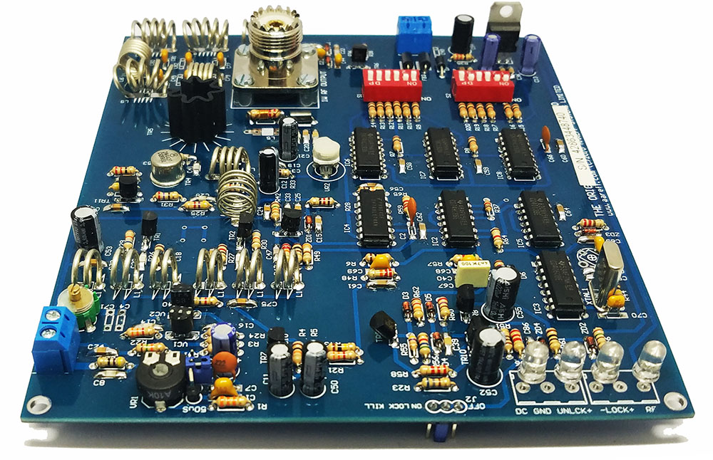
PCB LAYOUT – COMPONENTS FITTED

SCHEMATIC (PLL9)

CIRCUIT TESTING

If the 1 watt PLL is connected to a Veronica / Aareff Limiter Compressor or a Stereo Coder, pre-emphasis is not required. To disable the pre-emphasis, do not select 50uS or 75uS and remove the jumper completely. Store the jumper in a safe place just in case you need to restore the pre-emph for another application at a later date.

The 1W PLL features out of lock shutdown, this is a required for use in the EU. The diagram above shows how to set the jumper to activate it.>
1. Plug in 50 ohm dummy load (resistors soldered inside PL-259) DO NOT POWER THE CIRCUIT WITHOUT A 50 ohm LOAD CONNECTED TO THE SO-239.
2. Apply between 12 and 16 volts to the PCB position marked +15V (+) and 0V (-). DO NOT EXCEED 16V DC.
3. Choose a frequency from the attached LOOK-UP table and select the appropriate code on the transmitter DIP switches.
4. Adjust VC1 slowly until the RED LED starts to dim. Continue adjusting VC1 even more slowly, the RED LED will dim further or flicker, then the BLUE LED will illuminate. The BLUE LED indicates a locked condition.
5. Experiment with the adjustment of VC1 to find centre lock repeating step 4.
6. Apply audio at line level to the phono socket. Adjust the VR1 for correct FM deviation.
7. Switch off and remove dummy load. You are now ready to install the 1W PLL into your transmission system.
SPECIFICATIONS
The following tests were taken at 15V DC and the worst case measurement was recorded over the range -20 to +50 deg C.
| Frequency | 100KHz steps from 87.5 to 108MHz |
| RF Power Output | 1000mW to 1400mW into 50 Ohm load |
| Deviation Sensitivity Stability | +/-2% max |
| Spurious Emissions | >75dB rtc |
| Harmonic Emissions | >63dB rtc |
| Out of Lock RF Muting | >63dB rtc |
| Freq Stability | +/- 1 KHz max., typ. +/-300Hz |
| Freq Fine Adj (VC2) | > +/- 1000Hz |
| RF Output Connector | SO239 |
| Audio Input Sensitivity | 0.775 V rms for +/- 75 KHz |
| Signal To Noise Ratio | 80 dBu |
| Frequency Response | Flat from 30 Hz to 76 KHz |
| Pre-emphasis | (50uS/ 75uS/ None) Selectable |
| Audio Distortion | Better than 0.02 % THD |
| Audio Input Connector | Phono/ RCA type unbalanced sockets |
| Power Supply | 13.8V DC Regulated 650mA max. |
TROUBLE SHOOTING
No LEDs illuminated
1. Power supply is working and polarity
No or poor audio
1. Check audio source is connected to circuit properly
2. Set VR1 to mid position
3. Check joints, polarity and for shorts around components
‘Buzz’ on the audio
1. In the presence of a strong RF signal ‘Buzz’ may be generated in audio source. Unplug the audio source to establish whether that is the cause. If this cures the problem, try another audio source or move the audio source further away from the transmitter
2. Strong RF often generates a ‘buzz’ on some receivers. Try a receiver at a further distance away from the transmitter.
3. Is the power supply regulated
RF Unstable.
1. Is TR4 and TR5 flat down to PCB as shown in the construction details diagram of section 13
2. Is the SO-239 connected to a 50 ohm load
3. Are the coils soldered properly and fully down to the PCB
4. Check nuts and bolts are tight and soldered joint is okay on S0-239
5. Check joints, polarity and for shorts on all of the components around TR4 and TR5.
Due to the complexity of the circuit, other faults are more difficult to locate without test equipment. All of the components in the kit are high quality and brand new, it's very likely that a fault is down to the construction. Using the PCB legend and Component List, check that all components are in the correct positions and have the correct polarity.
Carefully check the PCB soldering. Excessive soldering may have shorted out adjacent tracks on the PCB. Solder splashing from the iron could have shorted out adjacent tracks. A magnifying glass or multimeter may help to find any small hairline short circuits not visible to the naked eye. All soldered joints should be shiny in appearance. Any dull looking soldering may be a ‘dry joint’, causing the circuit to malfunction. Re-solder dull looking joints.
If the circuit still has a fault after double checking everything, contact your supplier or Aareff via Post or Email. Describe in writing or with a diagram the exact problem and we will take steps to get you working
SOLDERING TIPS
For good soldered joints it is vital that the circuit board is clean and free of grease. If the board has become dirty or greasy, clean it down with meths or some other suitable electrical cleaning solvent before starting construction.
Keep everything clean, that’s the answer to successful soldering. The iron tip always needs be clean and shiny, if the iron looks all grey, black and burnt, the solder will not flow properly. A small piece of sponge dampened with water is ideal for cleaning the iron. After a few soldered joints, wipe the tip of the iron on the damp sponge to remove the dirt build up.
Always apply the iron to the joint first, this heats the joint up, then apply the solder. This will give the joint a shiny and cone shaped appearance, which is correct. Never put a blob of solder on the iron and then apply this blob of solder to the joint. This will not work because the blob of solder will not bond to the cold joint
CIRCUIT OPERATION
Section 1 - Voltage controlled oscillator

The main VHF voltage controlled oscillator or VCO is the heart of the transmitter and it is where the radio signal that will finally find it's way to antenna is generated. This VCO is a Hartley type configured to operate in push pull mode at half the final frequency. Two sets of back to back varicap diodes are connected across the main LC tank. One of the varicap diodes is used for frequency correction and the other is used for direct FM modulation. The varicap diode used for the modulation is DC biased to give optimum deviation linearity. The collector current from each one of the VCO transistors is drawn from the same point. At this point the combined current pulses are at double the VCO frequency. The current pulses are resonated into a sine wave across the DC feed inductor. Providing the VCO transistors are matched, the fundamental frequency cancels leaving the doubled frequency at a level of about +10dBm.
Section 2 - 100mW RF amplifier

Using a class A biased and stabilised common emitter amplifier the +10dBm is amplified up to +20dBm. The VCO is loosely coupled to the amplifier input with a small value of capacitance. The small capacitor across the amplifier emitter resistor increases the amplifier gain at the higher frequencies compensating for high frequency losses in the amplifier transistor. The DC feed inductor works with input capacitance to the next amplifier to form a good impedance match and some slight broad tuning from 88 to 108 MHz.
Section 3 - 1W RF amplifier

The final 1W amplifier is a common emitter transistor operated in single ended class B mode. The amplifier input is +20dBm and is derived from the output of the 100mW amplifier. The transistor collector develops the RF voltage over the DC feed choke. This point is then matched and filtered through a 10 pole of LC filter to produce 1W when terminated with 50 ohm resistance at the output socket. A small amount of the RF from the output socket is rectified through two high frequency diodes, then buffered with a small transistor to drive an LED to indicated power. The RF harmonics at the output are at -65 dB rtc.
Section 4 - VHF fixed divider

A low power high impedance emitter follower transistor takes a small amount of RF signal from half frequency side of VCO. This signal is interfaced to the first divider IC 74ALS74. The IC is a high speed dual flip-flop. The flip flops are cascaded to make a divide by four stage. If the transmitter operating frequency is 100 MHz, the VCO is 50 MHz and this results in a divided output of 12.5 MHz.
Section 5 - Count by N

The main counter clock input is the 12.5 MHz signal from the VHF fixed divider. Three 74LS193 ICs are cascaded to form a count down arrangement. A 12 bit input is momentarily latched into the ICs from two 6 way dil switch banks. The 12 bit number is decrement by one for every 12.5 MHz clock pulse. If the dil switches are set to give a 12 bit number of 1000 in decimal, the 12 bit number will reach zero following a count of 1000 of the 12.5 MHz clock pulses, at this point the last IC in the chain signals the zero with an output pulse. This output pulse sends a signal back to the three counter ICs to once again momentarily latch the 12 bit input from the dip switches into the ICs and starts the whole countdown process again, then again and again and so on. The repetition of the output pulse is 12.5 KHz.
Section 6 - Pulse to square conversion
It is the 12.5 KHz count by N output pulse that will ultimately be compared to the quartz crystal oscillator in a later circuit stage. Unfortunately the the 12.5 KHz pulse is very narrow with a mark space ratio of about 1000:1, this is interfaced to a 74LS76 flip flop IC . The IC output results in a clean 1:1 mark space ratio square wave at 6.25 KHz. This square wave is the final output of the divider chain.
Section 7 - Crystal reference oscillator

The crystal reference oscillator is based around the cmos IC 4060. This IC features 14 cascaded flip flops, also know as a 14 bit ripple counter. It also features a built in amplifier to resonate the crystal across. A 6.4 MHz crystal is connected to the IC. A small adjustable capacitor is placed in parallel with the crystal load capacitance. This allows the crystal frequency to fine adjusted. The output of Q10 or cascaded flip flop number 10 is used. This divides the crystal frequency of 6.4 MHz by 1024 resulting in a clean square wave of 6.25 KHz. This square wave is the final output of the crystal reference.
Section 8 - XOR phase detector


The 6.25 KHz final divider output and the 6.25 KHz final crystal reference are applied to a 2 input XOR gate. This gate compares the two frequencies. If the two frequencies are exactly the same with a 90 degree phase shift between them, the output of the gate is a 1:1 mark space ratio square wave at 12.5 KHz. If the transmitter VCO frequency starts to drift, usually due to temperature variations, the 6.25 KHz final divider output will also drift. The XOR gate detects this as a phase change compared to the 6.25 KHz crystal reference and the mark space ratio at output of the XOR gate changes. Using an RC integrator on the output of the XOR gate results in a DC voltage from 0 to 5 V representing the transmitter frequency drift. This DC voltage is fed through a second RC integrator to produce the phase correction voltage and remove any further residual 12.5 KHz. The phase correction voltage is applied to the frequency correction varicap diode in the VCO forming a phase locked loop. A simple RC snubber circuit is also connected to ground from the phase correction voltage to prevent the loop hunting or bouncing up and down.
Section 9 - Lock indications


The output from the XOR gate is also taken to a second RC integrator to convert the changing mark space ratio into a DC voltage. If the transmitter is completely unlocked the DC voltage rises up an down continuously. This signal is passed through an RC high pass filter to leave only the AC component. The AC signal is rectified back to DC and passed through some buffering and inverting transistors to indicate unlocked and locked on two LEDs. This DC voltage representing an unlocked condition is also taken to the base of a small RF transistor that is across the input of the 100mW RF amplifier and ground. In the unlocked condition the RF is completely shunted or crow barred to ground. Shunting the RF to ground at this point provides more than -60 dBc of RF suppression.
NEED TO BUY ONE?
DIL SWITCH (S2 and S1)
| MHz | 1 | 2 | 3 | 4 | 5 | 6 | 1 | 2 | 3 | 4 | 5 | 6 | |
|---|---|---|---|---|---|---|---|---|---|---|---|---|---|
| 87.5 | ON | ON | OFF | OFF | ON | OFF | OFF | ON | OFF | ON | OFF | ON | |
| 87.6 | ON | ON | OFF | OFF | ON | OFF | OFF | ON | OFF | ON | OFF | OFF | |
| 87.7 | ON | ON | OFF | OFF | ON | OFF | OFF | ON | OFF | OFF | ON | ON | |
| 87.8 | ON | ON | OFF | OFF | ON | OFF | OFF | ON | OFF | OFF | ON | OFF | |
| 87.9 | ON | ON | OFF | OFF | ON | OFF | OFF | ON | OFF | OFF | OFF | ON | |
| 88 | ON | ON | OFF | OFF | ON | OFF | OFF | ON | OFF | OFF | OFF | OFF | |
| 88.1 | ON | ON | OFF | OFF | ON | OFF | OFF | OFF | ON | ON | ON | ON | |
| 88.2 | ON | ON | OFF | OFF | ON | OFF | OFF | OFF | ON | ON | ON | OFF | |
| 88.3 | ON | ON | OFF | OFF | ON | OFF | OFF | OFF | ON | ON | OFF | ON | |
| 88.4 | ON | ON | OFF | OFF | ON | OFF | OFF | OFF | ON | ON | OFF | OFF | |
| 88.5 | ON | ON | OFF | OFF | ON | OFF | OFF | OFF | ON | OFF | ON | ON | |
| 88.6 | ON | ON | OFF | OFF | ON | OFF | OFF | OFF | ON | OFF | ON | OFF | |
| 88.7 | ON | ON | OFF | OFF | ON | OFF | OFF | OFF | ON | OFF | OFF | ON | |
| 88.8 | ON | ON | OFF | OFF | ON | OFF | OFF | OFF | ON | OFF | OFF | OFF | |
| 88.9 | ON | ON | OFF | OFF | ON | OFF | OFF | OFF | OFF | ON | ON | ON | |
| 89 | ON | ON | OFF | OFF | ON | OFF | OFF | OFF | OFF | ON | ON | OFF | |
| 89.1 | ON | ON | OFF | OFF | ON | OFF | OFF | OFF | OFF | ON | OFF | ON | |
| 89.2 | ON | ON | OFF | OFF | ON | OFF | OFF | OFF | OFF | ON | OFF | OFF | |
| 89.3 | ON | ON | OFF | OFF | ON | OFF | OFF | OFF | OFF | OFF | ON | ON | |
| 89.4 | ON | ON | OFF | OFF | ON | OFF | OFF | OFF | OFF | OFF | ON | OFF | |
| 89.5 | ON | ON | OFF | OFF | ON | OFF | OFF | OFF | OFF | OFF | OFF | ON | |
| 89.6 | ON | ON | OFF | OFF | ON | OFF | OFF | OFF | OFF | OFF | OFF | OFF | |
| 89.7 | ON | ON | OFF | OFF | OFF | ON | ON | ON | ON | ON | ON | ON | |
| 89.8 | ON | ON | OFF | OFF | OFF | ON | ON | ON | ON | ON | ON | OFF | |
| 89.9 | ON | ON | OFF | OFF | OFF | ON | ON | ON | ON | ON | OFF | ON | |
| 90 | ON | ON | OFF | OFF | OFF | ON | ON | ON | ON | ON | OFF | OFF | |
| 90.1 | ON | ON | OFF | OFF | OFF | ON | ON | ON | ON | OFF | ON | ON | |
| 90.2 | ON | ON | OFF | OFF | OFF | ON | ON | ON | ON | OFF | ON | OFF | |
| 90.3 | ON | ON | OFF | OFF | OFF | ON | ON | ON | ON | OFF | OFF | ON | |
| 90.4 | ON | ON | OFF | OFF | OFF | ON | ON | ON | ON | OFF | OFF | OFF | |
| 90.5 | ON | ON | OFF | OFF | OFF | ON | ON | ON | OFF | ON | ON | ON | |
| 90.6 | ON | ON | OFF | OFF | OFF | ON | ON | ON | OFF | ON | ON | OFF | |
| 90.7 | ON | ON | OFF | OFF | OFF | ON | ON | ON | OFF | ON | OFF | ON | |
| 90.8 | ON | ON | OFF | OFF | OFF | ON | ON | ON | OFF | ON | OFF | OFF | |
| 90.9 | ON | ON | OFF | OFF | OFF | ON | ON | ON | OFF | OFF | ON | ON | |
| 91 | ON | ON | OFF | OFF | OFF | ON | ON | ON | OFF | OFF | ON | OFF | |
| 91.1 | ON | ON | OFF | OFF | OFF | ON | ON | ON | OFF | OFF | OFF | ON | |
| 91.2 | ON | ON | OFF | OFF | OFF | ON | ON | ON | OFF | OFF | OFF | OFF | |
| 91.3 | ON | ON | OFF | OFF | OFF | ON | ON | OFF | ON | ON | ON | ON | |
| 91.4 | ON | ON | OFF | OFF | OFF | ON | ON | OFF | ON | ON | ON | OFF | |
| 91.5 | ON | ON | OFF | OFF | OFF | ON | ON | OFF | ON | ON | OFF | ON | |
| 91.6 | ON | ON | OFF | OFF | OFF | ON | ON | OFF | ON | ON | OFF | OFF | |
| 91.7 | ON | ON | OFF | OFF | OFF | ON | ON | OFF | ON | OFF | ON | ON | |
| 91.8 | ON | ON | OFF | OFF | OFF | ON | ON | OFF | ON | OFF | ON | OFF | |
| 91.9 | ON | ON | OFF | OFF | OFF | ON | ON | OFF | ON | OFF | OFF | ON | |
| 92 | ON | ON | OFF | OFF | OFF | ON | ON | OFF | ON | OFF | OFF | OFF | |
| 92.1 | ON | ON | OFF | OFF | OFF | ON | ON | OFF | OFF | ON | ON | ON | |
| 92.2 | ON | ON | OFF | OFF | OFF | ON | ON | OFF | OFF | ON | ON | OFF | |
| 92.3 | ON | ON | OFF | OFF | OFF | ON | ON | OFF | OFF | ON | OFF | ON | |
| 92.4 | ON | ON | OFF | OFF | OFF | ON | ON | OFF | OFF | ON | OFF | OFF | |
| 92.5 | ON | ON | OFF | OFF | OFF | ON | ON | OFF | OFF | OFF | ON | ON | |
| 92.6 | ON | ON | OFF | OFF | OFF | ON | ON | OFF | OFF | OFF | ON | OFF | |
| 92.7 | ON | ON | OFF | OFF | OFF | ON | ON | OFF | OFF | OFF | OFF | ON | |
| 92.8 | ON | ON | OFF | OFF | OFF | ON | ON | OFF | OFF | OFF | OFF | OFF | |
| 92.9 | ON | ON | OFF | OFF | OFF | ON | OFF | ON | ON | ON | ON | ON | |
| 93 | ON | ON | OFF | OFF | OFF | ON | OFF | ON | ON | ON | ON | OFF | |
| 93.1 | ON | ON | OFF | OFF | OFF | ON | OFF | ON | ON | ON | OFF | ON | |
| 93.2 | ON | ON | OFF | OFF | OFF | ON | OFF | ON | ON | ON | OFF | OFF | |
| 93.3 | ON | ON | OFF | OFF | OFF | ON | OFF | ON | ON | OFF | ON | ON | |
| 93.4 | ON | ON | OFF | OFF | OFF | ON | OFF | ON | ON | OFF | ON | OFF | |
| 93.5 | ON | ON | OFF | OFF | OFF | ON | OFF | ON | ON | OFF | OFF | ON | |
| 93.6 | ON | ON | OFF | OFF | OFF | ON | OFF | ON | ON | OFF | OFF | OFF | |
| 93.7 | ON | ON | OFF | OFF | OFF | ON | OFF | ON | OFF | ON | ON | ON | |
| 93.8 | ON | ON | OFF | OFF | OFF | ON | OFF | ON | OFF | ON | ON | OFF | |
| 93.9 | ON | ON | OFF | OFF | OFF | ON | OFF | ON | OFF | ON | OFF | ON | |
| 94 | ON | ON | OFF | OFF | OFF | ON | OFF | ON | OFF | ON | OFF | OFF | |
| 94.1 | ON | ON | OFF | OFF | OFF | ON | OFF | ON | OFF | OFF | ON | ON | |
| 94.2 | ON | ON | OFF | OFF | OFF | ON | OFF | ON | OFF | OFF | ON | OFF | |
| 94.3 | ON | ON | OFF | OFF | OFF | ON | OFF | ON | OFF | OFF | OFF | ON | |
| 94.4 | ON | ON | OFF | OFF | OFF | ON | OFF | ON | OFF | OFF | OFF | OFF | |
| 94.5 | ON | ON | OFF | OFF | OFF | ON | OFF | OFF | ON | ON | ON | ON | |
| 94.6 | ON | ON | OFF | OFF | OFF | ON | OFF | OFF | ON | ON | ON | OFF | |
| 94.7 | ON | ON | OFF | OFF | OFF | ON | OFF | OFF | ON | ON | OFF | ON | |
| 94.8 | ON | ON | OFF | OFF | OFF | ON | OFF | OFF | ON | ON | OFF | OFF | |
| 94.9 | ON | ON | OFF | OFF | OFF | ON | OFF | OFF | ON | OFF | ON | ON | |
| 95 | ON | ON | OFF | OFF | OFF | ON | OFF | OFF | ON | OFF | ON | OFF | |
| 95.1 | ON | ON | OFF | OFF | OFF | ON | OFF | OFF | ON | OFF | OFF | ON | |
| 95.2 | ON | ON | OFF | OFF | OFF | ON | OFF | OFF | ON | OFF | OFF | OFF | |
| 95.3 | ON | ON | OFF | OFF | OFF | ON | OFF | OFF | OFF | ON | ON | ON | |
| 95.4 | ON | ON | OFF | OFF | OFF | ON | OFF | OFF | OFF | ON | ON | OFF | |
| 95.5 | ON | ON | OFF | OFF | OFF | ON | OFF | OFF | OFF | ON | OFF | ON | |
| 95.6 | ON | ON | OFF | OFF | OFF | ON | OFF | OFF | OFF | ON | OFF | OFF | |
| 95.7 | ON | ON | OFF | OFF | OFF | ON | OFF | OFF | OFF | OFF | ON | ON | |
| 95.8 | ON | ON | OFF | OFF | OFF | ON | OFF | OFF | OFF | OFF | ON | OFF | |
| 95.9 | ON | ON | OFF | OFF | OFF | ON | OFF | OFF | OFF | OFF | OFF | ON | |
| 96 | ON | ON | OFF | OFF | OFF | ON | OFF | OFF | OFF | OFF | OFF | OFF | |
| 96.1 | ON | ON | OFF | OFF | OFF | OFF | ON | ON | ON | ON | ON | ON | |
| 96.2 | ON | ON | OFF | OFF | OFF | OFF | ON | ON | ON | ON | ON | OFF | |
| 96.3 | ON | ON | OFF | OFF | OFF | OFF | ON | ON | ON | ON | OFF | ON | |
| 96.4 | ON | ON | OFF | OFF | OFF | OFF | ON | ON | ON | ON | OFF | OFF | |
| 96.5 | ON | ON | OFF | OFF | OFF | OFF | ON | ON | ON | OFF | ON | ON | |
| 96.6 | ON | ON | OFF | OFF | OFF | OFF | ON | ON | ON | OFF | ON | OFF | |
| 96.7 | ON | ON | OFF | OFF | OFF | OFF | ON | ON | ON | OFF | OFF | ON | |
| 96.8 | ON | ON | OFF | OFF | OFF | OFF | ON | ON | ON | OFF | OFF | OFF | |
| 96.9 | ON | ON | OFF | OFF | OFF | OFF | ON | ON | OFF | ON | ON | ON | |
| 97 | ON | ON | OFF | OFF | OFF | OFF | ON | ON | OFF | ON | ON | OFF | |
| 97.1 | ON | ON | OFF | OFF | OFF | OFF | ON | ON | OFF | ON | OFF | ON | |
| 97.2 | ON | ON | OFF | OFF | OFF | OFF | ON | ON | OFF | ON | OFF | OFF | |
| 97.3 | ON | ON | OFF | OFF | OFF | OFF | ON | ON | OFF | OFF | ON | ON | |
| 97.4 | ON | ON | OFF | OFF | OFF | OFF | ON | ON | OFF | OFF | ON | OFF | |
| 97.5 | ON | ON | OFF | OFF | OFF | OFF | ON | ON | OFF | OFF | OFF | ON | |
| 97.6 | ON | ON | OFF | OFF | OFF | OFF | ON | ON | OFF | OFF | OFF | OFF | |
| 97.7 | ON | ON | OFF | OFF | OFF | OFF | ON | OFF | ON | ON | ON | ON | |
| 97.8 | ON | ON | OFF | OFF | OFF | OFF | ON | OFF | ON | ON | ON | OFF | |
| 97.9 | ON | ON | OFF | OFF | OFF | OFF | ON | OFF | ON | ON | OFF | ON | |
| 98 | ON | ON | OFF | OFF | OFF | OFF | ON | OFF | ON | ON | OFF | OFF | |
| 98.1 | ON | ON | OFF | OFF | OFF | OFF | ON | OFF | ON | OFF | ON | ON | |
| 98.2 | ON | ON | OFF | OFF | OFF | OFF | ON | OFF | ON | OFF | ON | OFF | |
| 98.3 | ON | ON | OFF | OFF | OFF | OFF | ON | OFF | ON | OFF | OFF | ON | |
| 98.4 | ON | ON | OFF | OFF | OFF | OFF | ON | OFF | ON | OFF | OFF | OFF | |
| 98.5 | ON | ON | OFF | OFF | OFF | OFF | ON | OFF | OFF | ON | ON | ON | |
| 98.6 | ON | ON | OFF | OFF | OFF | OFF | ON | OFF | OFF | ON | ON | OFF | |
| 98.7 | ON | ON | OFF | OFF | OFF | OFF | ON | OFF | OFF | ON | OFF | ON | |
| 98.8 | ON | ON | OFF | OFF | OFF | OFF | ON | OFF | OFF | ON | OFF | OFF | |
| 98.9 | ON | ON | OFF | OFF | OFF | OFF | ON | OFF | OFF | OFF | ON | ON | |
| 99 | ON | ON | OFF | OFF | OFF | OFF | ON | OFF | OFF | OFF | ON | OFF | |
| 99.1 | ON | ON | OFF | OFF | OFF | OFF | ON | OFF | OFF | OFF | OFF | ON | |
| 99.2 | ON | ON | OFF | OFF | OFF | OFF | ON | OFF | OFF | OFF | OFF | OFF | |
| 99.3 | ON | ON | OFF | OFF | OFF | OFF | OFF | ON | ON | ON | ON | ON | |
| 99.4 | ON | ON | OFF | OFF | OFF | OFF | OFF | ON | ON | ON | ON | OFF | |
| 99.5 | ON | ON | OFF | OFF | OFF | OFF | OFF | ON | ON | ON | OFF | ON | |
| 99.6 | ON | ON | OFF | OFF | OFF | OFF | OFF | ON | ON | ON | OFF | OFF | |
| 99.7 | ON | ON | OFF | OFF | OFF | OFF | OFF | ON | ON | OFF | ON | ON | |
| 99.8 | ON | ON | OFF | OFF | OFF | OFF | OFF | ON | ON | OFF | ON | OFF | |
| 99.9 | ON | ON | OFF | OFF | OFF | OFF | OFF | ON | ON | OFF | OFF | ON | |
| 100 | ON | ON | OFF | OFF | OFF | OFF | OFF | ON | ON | OFF | OFF | OFF | |
| 100.1 | ON | ON | OFF | OFF | OFF | OFF | OFF | ON | OFF | ON | ON | ON | |
| 100.2 | ON | ON | OFF | OFF | OFF | OFF | OFF | ON | OFF | ON | ON | OFF | |
| 100.3 | ON | ON | OFF | OFF | OFF | OFF | OFF | ON | OFF | ON | OFF | ON | |
| 100.4 | ON | ON | OFF | OFF | OFF | OFF | OFF | ON | OFF | ON | OFF | OFF | |
| 100.5 | ON | ON | OFF | OFF | OFF | OFF | OFF | ON | OFF | OFF | ON | ON | |
| 100.6 | ON | ON | OFF | OFF | OFF | OFF | OFF | ON | OFF | OFF | ON | OFF | |
| 100.7 | ON | ON | OFF | OFF | OFF | OFF | OFF | ON | OFF | OFF | OFF | ON | |
| 100.8 | ON | ON | OFF | OFF | OFF | OFF | OFF | ON | OFF | OFF | OFF | OFF | |
| 100.9 | ON | ON | OFF | OFF | OFF | OFF | OFF | OFF | ON | ON | ON | ON | |
| 101 | ON | ON | OFF | OFF | OFF | OFF | OFF | OFF | ON | ON | ON | OFF | |
| 101.1 | ON | ON | OFF | OFF | OFF | OFF | OFF | OFF | ON | ON | OFF | ON | |
| 101.2 | ON | ON | OFF | OFF | OFF | OFF | OFF | OFF | ON | ON | OFF | OFF | |
| 101.3 | ON | ON | OFF | OFF | OFF | OFF | OFF | OFF | ON | OFF | ON | ON | |
| 101.4 | ON | ON | OFF | OFF | OFF | OFF | OFF | OFF | ON | OFF | ON | OFF | |
| 101.5 | ON | ON | OFF | OFF | OFF | OFF | OFF | OFF | ON | OFF | OFF | ON | |
| 101.6 | ON | ON | OFF | OFF | OFF | OFF | OFF | OFF | ON | OFF | OFF | OFF | |
| 101.7 | ON | ON | OFF | OFF | OFF | OFF | OFF | OFF | OFF | ON | ON | ON | |
| 101.8 | ON | ON | OFF | OFF | OFF | OFF | OFF | OFF | OFF | ON | ON | OFF | |
| 101.9 | ON | ON | OFF | OFF | OFF | OFF | OFF | OFF | OFF | ON | OFF | ON | |
| 102 | ON | ON | OFF | OFF | OFF | OFF | OFF | OFF | OFF | ON | OFF | OFF | |
| 102.1 | ON | ON | OFF | OFF | OFF | OFF | OFF | OFF | OFF | OFF | ON | ON | |
| 102.2 | ON | ON | OFF | OFF | OFF | OFF | OFF | OFF | OFF | OFF | ON | OFF | |
| 102.3 | ON | ON | OFF | OFF | OFF | OFF | OFF | OFF | OFF | OFF | OFF | ON | |
| 102.4 | ON | ON | OFF | OFF | OFF | OFF | OFF | OFF | OFF | OFF | OFF | OFF | |
| 102.5 | ON | OFF | ON | ON | ON | ON | ON | ON | ON | ON | ON | ON | |
| 102.6 | ON | OFF | ON | ON | ON | ON | ON | ON | ON | ON | ON | OFF | |
| 102.7 | ON | OFF | ON | ON | ON | ON | ON | ON | ON | ON | OFF | ON | |
| 102.8 | ON | OFF | ON | ON | ON | ON | ON | ON | ON | ON | OFF | OFF | |
| 102.9 | ON | OFF | ON | ON | ON | ON | ON | ON | ON | OFF | ON | ON | |
| 103 | ON | OFF | ON | ON | ON | ON | ON | ON | ON | OFF | ON | OFF | |
| 103.1 | ON | OFF | ON | ON | ON | ON | ON | ON | ON | OFF | OFF | ON | |
| 103.2 | ON | OFF | ON | ON | ON | ON | ON | ON | ON | OFF | OFF | OFF | |
| 103.3 | ON | OFF | ON | ON | ON | ON | ON | ON | OFF | ON | ON | ON | |
| 103.4 | ON | OFF | ON | ON | ON | ON | ON | ON | OFF | ON | ON | OFF | |
| 103.5 | ON | OFF | ON | ON | ON | ON | ON | ON | OFF | ON | OFF | ON | |
| 103.6 | ON | OFF | ON | ON | ON | ON | ON | ON | OFF | ON | OFF | OFF | |
| 103.7 | ON | OFF | ON | ON | ON | ON | ON | ON | OFF | OFF | ON | ON | |
| 103.8 | ON | OFF | ON | ON | ON | ON | ON | ON | OFF | OFF | ON | OFF | |
| 103.9 | ON | OFF | ON | ON | ON | ON | ON | ON | OFF | OFF | OFF | ON | |
| 104 | ON | OFF | ON | ON | ON | ON | ON | ON | OFF | OFF | OFF | OFF | |
| 104.1 | ON | OFF | ON | ON | ON | ON | ON | OFF | ON | ON | ON | ON | |
| 104.2 | ON | OFF | ON | ON | ON | ON | ON | OFF | ON | ON | ON | OFF | |
| 104.3 | ON | OFF | ON | ON | ON | ON | ON | OFF | ON | ON | OFF | ON | |
| 104.4 | ON | OFF | ON | ON | ON | ON | ON | OFF | ON | ON | OFF | OFF | |
| 104.5 | ON | OFF | ON | ON | ON | ON | ON | OFF | ON | OFF | ON | ON | |
| 104.6 | ON | OFF | ON | ON | ON | ON | ON | OFF | ON | OFF | ON | OFF | |
| 104.7 | ON | OFF | ON | ON | ON | ON | ON | OFF | ON | OFF | OFF | ON | |
| 104.8 | ON | OFF | ON | ON | ON | ON | ON | OFF | ON | OFF | OFF | OFF | |
| 104.9 | ON | OFF | ON | ON | ON | ON | ON | OFF | OFF | ON | ON | ON | |
| 105 | ON | OFF | ON | ON | ON | ON | ON | OFF | OFF | ON | ON | OFF | |
| 105.1 | ON | OFF | ON | ON | ON | ON | ON | OFF | OFF | ON | OFF | ON | |
| 105.2 | ON | OFF | ON | ON | ON | ON | ON | OFF | OFF | ON | OFF | OFF | |
| 105.3 | ON | OFF | ON | ON | ON | ON | ON | OFF | OFF | OFF | ON | ON | |
| 105.4 | ON | OFF | ON | ON | ON | ON | ON | OFF | OFF | OFF | ON | OFF | |
| 105.5 | ON | OFF | ON | ON | ON | ON | ON | OFF | OFF | OFF | OFF | ON | |
| 105.6 | ON | OFF | ON | ON | ON | ON | ON | OFF | OFF | OFF | OFF | OFF | |
| 105.7 | ON | OFF | ON | ON | ON | ON | OFF | ON | ON | ON | ON | ON | |
| 105.8 | ON | OFF | ON | ON | ON | ON | OFF | ON | ON | ON | ON | OFF | |
| 105.9 | ON | OFF | ON | ON | ON | ON | OFF | ON | ON | ON | OFF | ON | |
| 106 | ON | OFF | ON | ON | ON | ON | OFF | ON | ON | ON | OFF | OFF | |
| 106.1 | ON | OFF | ON | ON | ON | ON | OFF | ON | ON | OFF | ON | ON | |
| 106.2 | ON | OFF | ON | ON | ON | ON | OFF | ON | ON | OFF | ON | OFF | |
| 106.3 | ON | OFF | ON | ON | ON | ON | OFF | ON | ON | OFF | OFF | ON | |
| 106.4 | ON | OFF | ON | ON | ON | ON | OFF | ON | ON | OFF | OFF | OFF | |
| 106.5 | ON | OFF | ON | ON | ON | ON | OFF | ON | OFF | ON | ON | ON | |
| 106.6 | ON | OFF | ON | ON | ON | ON | OFF | ON | OFF | ON | ON | OFF | |
| 106.7 | ON | OFF | ON | ON | ON | ON | OFF | ON | OFF | ON | OFF | ON | |
| 106.8 | ON | OFF | ON | ON | ON | ON | OFF | ON | OFF | ON | OFF | OFF | |
| 106.9 | ON | OFF | ON | ON | ON | ON | OFF | ON | OFF | OFF | ON | ON | |
| 107 | ON | OFF | ON | ON | ON | ON | OFF | ON | OFF | OFF | ON | OFF | |
| 107.1 | ON | OFF | ON | ON | ON | ON | OFF | ON | OFF | OFF | OFF | ON | |
| 107.2 | ON | OFF | ON | ON | ON | ON | OFF | ON | OFF | OFF | OFF | OFF | |
| 107.3 | ON | OFF | ON | ON | ON | ON | OFF | OFF | ON | ON | ON | ON | |
| 107.4 | ON | OFF | ON | ON | ON | ON | OFF | OFF | ON | ON | ON | OFF | |
| 107.5 | ON | OFF | ON | ON | ON | ON | OFF | OFF | ON | ON | OFF | ON | |
| 107.6 | ON | OFF | ON | ON | ON | ON | OFF | OFF | ON | ON | OFF | OFF | |
| 107.7 | ON | OFF | ON | ON | ON | ON | OFF | OFF | ON | OFF | ON | ON | |
| 107.8 | ON | OFF | ON | ON | ON | ON | OFF | OFF | ON | OFF | ON | OFF | |
| 107.9 | ON | OFF | ON | ON | ON | ON | OFF | OFF | ON | OFF | OFF | ON | |
| 108 | ON | OFF | ON | ON | ON | ON | OFF | OFF | ON | OFF | OFF | OFF |
ROHS
All components used in this apparatus are RoHS compliant and do not contain above the specified limits in any of the following restricted substances:
• Lead
• Hexavalent Chromium
• Mercury
• Cadmium
• Polybrominated Biphenyls (PBB's)
• Polybrominated Diphenylethers (PBDE's)
PRODUCT END OF LIFE
This apparatus must NOT be disposed of with other domestic waste.
We are fully committed to maintaining our responsibilities to the environment. Owners of apparatus that has reached the end of it's useful life can return it to us for recycling, recondition, reuse or proper disposal. You will be required to pay lowest cost postal service available to ship the apparatus to us. Before shipping please contact us for more important information.
DECLARATION OF CONFORMITY
AAREFF TRANSMISSION SYSTEMS SL
AVDA ANDALUCIA 1
LA ALFOQUIA-ZURGENA
04661
ALMERIA
ESPANA.
Paul Hollings
![]()

In Zurgena, Almería, Spain on 01 of November 2008, the equipment:
Original and Genuine Veronica® 1W PLL (1WPLLM) meets the essential requirements of the R&TTE directive
ETS 300 384/A1 ed.1 (1997-2002) Broadcasting Systems Transmitters FM sound broadcasting in very high frequency (VHF)
It should be noted that this cannot be legally used as a standalone unit. This sub assembly is designed and intended to be installed in a fully screened EMC enclosure with or without other sub assemblies. Any final design should be further tested to verify it meets the essential requirements of:
EN 301 489-11 V1.3.1 (2006-05) Electromagnetic compatibility and Radio Spectrum Matters (EMC) for radio equipment and services. Part 11: Specific conditions for transmitting the terrestrial sound broadcasting service.
2006/95/EC DIRECTIVE 2006/95/EC of 12 December 2006 on electrical equipment designed for use within certain voltage limits.
© 2009 Aareff Systems Limited
ALL RIGHTS RESERVED. Aareff is a trademark of Aareff Transmission Systems. All contents of this document including, but not limited to the images, logos, text, illustrations are protected by copyrights, trademarks and other intellectual property rights which are owned and controlled by Aareff Transmission Systems or by other parties that have licensed their material to Aareff Transmission Systems. This document in part or whole may not be copied, reproduced, republished, uploaded, posted or distributed in any way, including by e-mail, ftp or any other electronic means
Every care has been taken in the preparation of this document, errors in content, typographical or otherwise, may have occurred. If you have comments concerning its accuracy, please contact Aareff Systems Limited (UK)